The Answers:
1.1. About this FAQ
This FAQ attempts to gather knowledge about the Apple Lisa computer in a central place, whether technical or historical.The goal is to provide information that helps preserve existing Apple Lisa computers, aids in their repair, as well as provides historical and educational information about this historically significant machine.
Lisa used to be a trademark of Apple, Inc. Since I'm not a lawyer, I don't know the current status of this trademark, and ask that if Apple still holds this trademark, that you optionally visualize a trademark symbol following every instance of the word Lisa, Apple, Apple ]&Macintosh, iPod, PowerBook, MacBook Pro, ad vomitus, ditto for other registered or non-registered trademarks. Information in this FAQ was gathered from a variety of sources, including but not limited to, web searches for the words "Apple Lisa", the LisaList, David T. Craig's Lisa archives, various articles, books, the Sun Remarketing Lisa and Mac XL Do it Yourself Guide , personal knowledge and experience, and other materials that I've forgotten. Some of the documents were quoted verbatim, others paraphrased, so that they would better fit the FAQ format. In every instance, except for the knowledge in the backs of our minds, credit to the source was given. This FAQ is not connected with, nor sponsored by any commercial entities. Any mention of products, stores, websites, etc. is purely for informational use, because I've heard about it, or have used it. There are no commercial interests in anything listed herein. (i.e. the page listing 3.5" floppies.) If you find anything you'd like to add, or have corrections, suggestions, flames, or spam, please send them by email to mailto:lisafaq@sunder.net. Information in this FAQ is believed to be accurate, but might not be. Links to websites outside of this domain such as those to online stores (for example, the page listing 3.5" floppies) may vanish without notice or reason. Some of the repairs and procedures listed here are inherently dangerous as they involve work with high voltage components. Proceede with caution, and apply all possible precautions, but note that you do so at your own risk whether your have read this disclaimer or not. (Whatever happened to being responsible for your own actions? i.e. not jumping off a cliff because you saw it on Simpsons episode?) Donations of Lisa hardware (or other historical computer equipment), modern computers (AMD64, UltraSparc IV, MacBook Pro's or Powerbooks preferred), ipods, software, books, or good ol'e hard cash are very gladly accepted.
Information in this FAQ was gathered from a variety of sources, including but not limited to, web searches for the words "Apple Lisa", the
�(Comment on this answer)
2.1. What is the Apple Lisa?
The Apple Lisa is a computer built by Apple Computer, Inc. between 1979 and 1983. It is one of the first commercial machines to have a graphical user interface, use a mouse, and have an interface that contained icons, windows, pull down menus, dialog boxes.
About the Lisa's design
Although the Lisa is considered a microcomputer, it was designed by ex-minicomputer designers, and has minicomputer features. For exampled, it contains two CPU's (a Motorola 68000 and a 6504), and a COP421 microcontroller. The main processor is the 32 bit MC68000. The 6504 is used as a dedicated controller for the floppy drives. The COP421 microcontroller is used for the system clock, power management, keyboard and mouse interface.
The Lisa was designed to be a personal computer. This was a huge departure from both from the shared mainframe with multiple terminals model, as well as character, or text based, personal microcomputers computers. Unlike most mini or mainframe machines of the era, the Lisa provided multi-tasking for one user, rather than time sharing for many users.
The hardware design is clean, and contained features from high end micros. For example, it supports virtual memory (via a memory management unit that provides for both application multitasking as well as preventing one application from crashing another), hard drives, a serial communications controller that can talk to mainframes over SDLC, and so on.
The design of the case makes it easy for the end user to service the Lisa. Almost every card/device is user replaceable.
Various operating systems were developed for the Lisa hardware. Of these, the Lisa Office System has had the most influence and impact, and so deserves much of the credit for the significance of the Lisa.
About the Lisa Office System
The Lisa Office System is a very sophisticated OS that at its core has a lot of similarities to Unix (multitasking, virtual memory, MMU, named pipes as files, device control as files.)
On top of this the user is presented with a highly polished graphical user interface that uses a document oriented metaphor instead of the application oriented model of other computers. For example, you don't run LisaWrite to compose a memo. Instead, you tear off a sheet of stationary to compose your memo. You could then open a LisaCalc spreadsheet and copy and paste data into the memo from the spreadsheet. This is done through a mechanism similar to OpenDOC, or OLE (renamed to ActiveX.)
Documents, and filenames
Users don't have to use the "save" command in a File menu on documents unless they want to ensure that recent changes have been written to the disk, or want to immediately save and put away the file (which closes it).
There also is no File Open or File Save dialog box, which to this day plagues every modern GUI out there with a miniature finder/explorer that doesn't quite have the same functionality as the real thing, and causes frustration. This completed the illusion that icons expanded themselves to documents, or better said, that icons are documents. The Lisa had it right
Multiple documents can have the same file name. If you duplicate a LisaWrite document, you get two copies, both with the same name, without having a conflict! This is because the desktop names on the Lisa are virtual. Underneath the pretty GUI, the file system names things uniquely. Think of it this way, when a user makes a copy of a document for another using a photocopier, there are now two identical copies. The user doesn't have to explicitly rename one of them, or worry about document names.
The user never sees any of the underlying operating system files, so they can't harm the operating system by deleting its files.
Backups?
The Lisa Desktop is able to split a file that is greater than a 400K floppy across multiple floppies. When you attempt to copy it back to the hard drive, it asks you to insert the next floppy and says/The Lisa is reconstructing "filename" on "hard disk"./ You can back up your hard drive by simply dragging it to an empty floppy, and the Desktop Manager will ask you for another disk, and then another, until you have made a full backup.
Users don't need to launch a separate program to do backups.
Other Innovations
The Lisa also has features such as a built in screen saver that after a few minutes of inactivity will dim the screen to a user specified brightness.
Unlike most personal computers that have a big red switch to control power, the Lisa uses a software managed power supply. When the user presses the power switch, it acts as a special keystroke; instead of just powering off, the Lisa Office System puts all the files "away" (saving the changes), and then, once it is safe to do so, it tells the COP421 controller to power the Lisa off.
On the next power up, the Lisa will open all the windows and opened documents to the exact position where the user left off
This is similar to hibernating, sleeping, or standby on modern computers. Yet, all of this is done without swapping all of the Lisa's memory to disk, or keeping the main CPU in a low power state to preserve the contents of memory!
Instead, every Tool (Lisa Application) remembered where the user left off and resumes to the same position the next time the Lisa is powered. Compared to "modern" software packages, where it's up to the programmer to provide some option to save state, but requires the user to explicitly do so the next time that application is launched.
Summary
Many of the features of the Lisa hardware and Lisa Office System were lost as Apple switched to the Macintosh instead. Some, over time made their way back in, others showed up in various other operating systems, but none have the same look and feel as the Lisa, nor the same tight integration between applications, documents, operating system, and hardware. The only other machine with this high level of integration would be Apple's Newton.
(No, before you ask, in Lisa Office System, one does not drag the floppy to the trash can to eject it)
Lisa is a much nicer equivalent of a modern day office suite (with memory/storage/CPU limitations) but existed over 20 years ago.
These are the features that make this a great, and very unique machine, which was truly ahead of it's time.
Sadly, Lisa was replaced by a machine that was its mere shadow. The original Mac 128 was considered crippled when compared to the Lisa. With only 128K of RAM, it could only run one program at a time. To do any real work, an external floppy drive was required. The alternative was a horrible incessant swapping of floppies every few seconds.
Fortunately, the Mac has evolved over time, and while it lacks the same level of integration as the Lisa did 25 years ago, it has matured quite nicely.
�(Comment on this answer)
2.2. What books mention, or are about the Lisa?
There are quite a few books that have information about the Apple Lisa. There are some that are technical, and some about Apple, Inc., which contain mentions, or historical information about the Lisa. There's even a movie
Technical Lisa Books
- Apple Lisa: A User-Friendly handbook by Joseph Coleman Amazon
- Apple Lisa User's Handbook by Inc. Weber Systems Amazon
- The Complete Book of Lisa by Kurt J. Schmucker Amazon
- Macintosh Hardware Repair Secrets by Larry Pina Amazon
- The Apple Lisa Handbook by Michael J. Posner A Collection of quotes and clippings about the Lisa
Books of Historical Interest about the Lisa
- Mac Bathroom Reader by Owen W. Linzmayer much of the same information. Amazon
- Revolution in the Valley by Andy Hertzfeld, et al. Amazon whose text can also be found here: http://folklore.org
- West of Eden: The End of Innocence at Apple Computer by Frank Rose Amazon
- The Little Kingdom: The Private Story of Apple by Michael Moritz Amazon
There's even a movie
- The Pirates of Silicon Valley (Movie on DVD) movie website Amazon
�
(Comment on this answer)
2.3. What Lisa Websites are out there?
Apple Lisa Mailing List
- http://lowendmac.com/lists/lisa.html Lisa List - (defunct)
- https://lisalist2.com Lisa List2 - Replacement for the above.
The Apple Lisa Emulator and related
- http://lisaem.sunder.net LisaEm is the world's first fully functional Lisa emulator.
- http://lowendmac.com/hodges/07/0313.html Interview with Ray Arachelian, Creator of the Lisa Emulator, Ted Hodges, LEM
- http://slashdot.jp/interview/article.pl?sid=07/04/02/011220 Japanese translation of the above
- http://lowendmac.com/hodges/07/0227.html Lisa Emulator Released, Allows OS X and Windows Users to Experience Apple's Lisa, Ted Hodges, LEM
- http://slashdot.jp/mac/article.pl?sid=07/04/02/0132202 Japanese translation of the above.
- http://www.mactime.ru/Environ/WebObjects/mactime.woa/2/wa/Main?textid=6961&level1=mactimes&wosid=rrSRvMJJdYd7CdcLebqqKw Russian translation of the above?
- http://retromaccast.libsyn.com/index.php?post_id=196147 James and John interview Ray Arachelian at the Retro Mac Cast (m4a)
Unique, Fun Pages
- http://www.lisa2.com/ A Lisa being used as a webserver
- http://myoldmac.net/SELL/CompuBots.htm CompuBots - original Lisa artwork
- http://www.kreativekorp.com/kko/pixel/fonts.html Lisa Fonts for your Mac (scroll down about half way.)
- http://www.masswerk.at/schemes.htm Kaleidoscope Themes - including a Lisa one
- http://www.jg.org/folk/artists/fredsmall/applelisa.html The Heart of the Apple Lisa - song
Papers and Articles
- http://lowendmac.com/hodges/07/0402.html Using Apple's Lisa for Real Work - Ted Hodges, LEM
- http://retrobits.libsyn.com/index.php?post_id=175947 The Apple Lisa - podcast at RetroBits
- http://lisa.sunder.net/mirrors/Simon/Lisa/LisaLegacy/LegacyIndex.html The Legacy of the Apple Lisa Personal Computer: An Outsider's View, by David T. Craig
- http://members.safe-t.net/jwalker/programming/lisaLegacy/ The Legacy of the Apple Lisa Personal Computer: An Outsider's View, by David T. Craig (mirror)
- http://lowendmac.com/tech/lisa.html "The Innovative Lisa"
- http://www.guidebookgallery.org/articles/thelisacomputersystem "The Lisa Computer System" Byte Magazine Feb 1983
- http://lowendmac.com/musings/03/0120.html "Lisa's Legacy" on the Lisa's 20th Anniversary
- http://lowendmac.com/orchard/05/1005.html "A History of Apple's Lisa 1979-1986"
- http://www.pegasus3d.com/apple_screens.html Designing Lisa UI
- http://www.semaphorecorp.com/ss/toc.html Semaphore Signal - a Magazine for Lisa users
- http://web.archive.org/web/20040328125354/http://www.cs.berkeley.edu/~jasonh/cs39i-seminar/p40-perkins.pdfInventing the Apple Lisa Interface
- http://www.mprove.de/diplom/text/3.1.8_lisa.html Apple Lisa in Vision and Reality of Hypertext and Graphical User Interfaces
- http://en.wikipedia.org/wiki/Apple_Lisa WikiPedia entry for Apple Lisa
- http://folklore.org Folklore.org
- http://folklore.org/StoryView.py?project=Macintosh&story=Busy_Being_Born.txt Busy Being Born - Building the Lisa UI
- http://www.cyberlaw.com/cylw994.html Apple Loses Lawsuit
- http://lowendmac.com/orchard/05/1005.html A History of Apple's Lisa, 1979-1986
- http://www.mprove.de/diplom/text/3.1.8_lisa.html The Lisa part of Matthias Mueller-Prove's Master Thesis: Vision and Reality of Hypertext and Graphical User Interfaces
- http://www.cs.utc.edu/jdumas/cs460/papersfa02/applelisa/index.htm Apple Lisa Architecture - A Paper by Jon Freeland, Joslin Hendricks, Keith Powell, Sharad Tiwari from the University of Tennessee CS460 Fall 2005
- http://inventors.about.com/library/weekly/aa043099.htm Inventors of the Modern Computer - The History of the Graphical User Interface or GUI - The Apple Lisa (some incorrect specs though)
- Http://www.jagshouse.com/lisa2.html Whatever happened to the Lisa? Article by John C. Dvorak. at Jaghouse
- http://www.vcnet.com/bms/departments/innovation.html Microsoft Hall of Innovation Article mentions things borrowed from the Lisa
- http://www.mackido.com/Innovation/index.html MacKido Contributions Article Mentions who contributed what for Mac/Apple
- http://www.mackido.com/Interface/ui_history.html Microsoft, Apple and Xerox - The History of the Graphical User Interface
- http://www.usfca.edu/usf/turner/interface-history.html An Unofficial History of Advances in Computer Interfaces
- http://www.cs.cmu.edu/~amulet/papers/uihistory.tr.html A Brief History of Human Computer Interaction Technology
- http://news.com.com/2009-1041_3-6053877.html Apple's 30th Anniversary - Designing the Lisa and Mac UI's
- http://www.byte.com/art/9509/sec7/art24.htm Byte: 20 Spectacular Failures - One Paragraph on the Lisa
Photos
- http://tom.stepleton.com/catalog.php?show=2002-12-01 Beauty photos of Lisa
- http://www.macgeek.org/museum/applelisa1/ Pictures of an Apple Lisa 1
- http://www.guidebookgallery.org/extras/spotlights/lisa GUIde Book Gallery - see what the Lisa's UI looked like
- http://www.digibarn.com/collections/systems/apple-lisa1/index.html Apple Lisa 1 Pictures at DigiBarn
- http://www.digibarn.com/collections/systems/apple-lisa2xl/index.html Apple Lisa 2 and XL pictures at DigiBarn
Video
- http://www.digibarn.com/collections/movies/digibarn-tv/gui-movies/apple/ Apple GUI movies
- http://www.guidebookgallery.org/videos/lisatvad Apple Commercial featuring the Lisa and Kevin Costner
- http://www.esm.psu.edu/Faculty/Gray/graphics/movies/apple_lisa_kevin_costner_1983.mov another copy of the same
Museums, spec sheets, etc.
- http://www.binarydinosaurs.co.uk/Museum/Apple/lisa/index.php Lisa page at Binary Dinosaurs
- http://www.dgatx.com/computing/people/Apple/hs.html Timeline of Apple history
- http://www.old-computers.com/museum/computer.asp?c=265&st=1 Old Computers Lisa Page
- http://applemuseum.bott.org/ Apple Museum
- http://lowendmac.com/orchard/05/1005.html A History of Apple's Lisa, 1979-1986
- http://www.vintagemacmuseum.com/vmm-extras.html The Vintage Mac Museum
- http://fp3.antelecom.net/gcifu/applemuseum/ Greg Cifu's Apple Museum
- http://www.geocities.com/SiliconValley/Lakes/6757/LISA2.HTML Timeline and history
- http://www.fortunecity.com/marina/reach/435/lisa.htm Another Lisa history page
- http://www.lowendmac.com/lisa/index.shtml Low End Mac - Lisa Page
- http://www.macmothership.com/ Huge collection of Lisa advertising brochures, pictures, etc.
- http://www.apple-history.com/lisa.html Apple History on the Lisa
- http://apple2history.org/museum/computers_lisa/lisadesktop.html Lisa Desktop and Pix
- http://www.applefritter.com/node/3191 Lisa page at AppleFritter
- http://ruby.he.net/~sigma/xlisa.html X/Lisa Page
- http://www.brouhaha.com/~eric/retrocomputing/lisa/twiggy.html Good info on the Lisa's Twiggies
- http://www.sunrem.com/ Sun Remarketing
Lisa documentation and software
- http://vintage.tsfsc.com/the-archive/Apple%20Lisa/ Huge Lisa Archive (not all disk images work)
- http://www.1000bit.net/support/manuali/manuali.asp David Craig's docs.
- http://lisa.sunder.net/books.html Lisa manuals and books (in page by page gif or jpg format)
- http://www.whoopis.com/lisa/ "Raoul's Lisa/MacXL Tech Info and Software"
- http://www.macmothership.com/lisacontent/lisahome.html Lisa System and application Software
- ftp://wac.callapple.org/pub/66.223.113.50/pub/Lisa An extensive archive of Lisa Software
- http://pastis.dyndns.org/LisaSoftware/ lisa software
Old Web Pages Mirrored
- http://lisa.sunder.net/mirrors/Simon/Lisa/Index.html Mirror of simon@atomicnet.com.au Circa Jan 1999
- http://lisa.sunder.net/mirrors/desieh/HISTORY.HTM Partial Mirror of Desie Hay's (desieh@southcom.com.au) Site Circa Nov 1998
- http://web.archive.org/web/19980212221412/galena.tjs.org/~tom/ Tom Stepleton's Web page (Internet Archive)
Search engine indexes
- http://dmoz.org/Computers/Systems/Apple/Lisa/
- http://images.google.com/images?q=apple+lisa&hl=en Google Images of Lisa
- http://search.ask.com/web?q=apple+lisa&qsrc=0&o=0 Teoma/Ask.com Lisa search
Replacement Lisa Hardware
- http://sigmasevensystems.com/xprofile The X/ProFile is a commercial replacement for the Lisa and Apple II or ///'s.
- http://john.ccac.rwth-aachen.de:8000/patrick/idefile.htm IDE-File is a non-comercial DYI project.
- http://tinyurl.com/2hw3vd eBay Search for Lisa (had to use tiny url as the target url is monstrous.)
(Comment on this answer)
3.1. My Lisa doesn't work. What general things can I check or do?
If the Lisa seems to turn on, but you don't see anything on the screen, the brightness may be set too low. Try adjusting the display controls (on the rear above the power cord).There are safety interlock switches that are engaged by the front and back covers. If these covers are not properly seated, the Lisa will not turn-on.
The front panel interlock switch is at the lower left. The rear panel interlock switch is near the top of the power supply.
For the most part, the interlock switches are for the safety of the Lisa, as it is difficult to reach dangerous voltages with only the front and back removed. The interlock switches can by defeated using folded cardboard or some other non-metallic item to depress the switch while the cover is removed. Use due care and proceed at your own risk if you operate your Lisa with any covers removed.
A used Lisa may not turn on because it is missing some component. In order to turn on, a Lisa requires:
- power supply
- card cage with motherboard
- I/O board
In order to show something on the screen, a Lisa also requires:
- CPU board
- one or two memory boards
- CRT, video card, and flyback transformer (the latter two are hidden in the chassis behind the CRT)
It is common for a Lisa to not power up or work properly due to poor contacts, below is a procedure for cleaning the contacts:
When handling Lisa components, take care to prevent damage due to ESD (electrostatic discharge).
Take out the Power Supply and card cage, and remove the CPU, I/O, and memory boards, as well as any expansion slot cards. Examine both sides of the card-edge connectors of each. Clean them with electronic contact cleaner or alcohol, and for extreme cases, a pencil eraser (be very gentle or the gold plating will be erased). Make sure that there's no oxidation left (or rubber from the eraser). Examine and if necessary, clean the card-edge receptacles.
Unplug any floppy/twiggy drives and any hard drives. Check their connectors are straight and clean.
Reseat the cards and make sure that they make contact properly. Some cards develop a warp and may not make contact all along the card edge.
Try to power the Lisa on with just the I/O board plugged in.
If that works, shut the Lisa off (you may have to pull out the power cord), and insert the CPU board without memory. This should cause the Lisa to beep and perhaps show an alternating video pattern (since there is no memory for the display.)
If this works, power the Lisa off again, insert a single memory board in the first slot. Power the Lisa on. If it doesn't work, swap it with another memory board. If it doesn't work, try the other slot. If it still doesn't work, you may have a bad memory board (or a bad CPU board.)
�(Comment on this answer)
3.2. What hardware upgrades exist for the Lisa?
Apple products
- Dual Parallel Port Expansion Card
- 512KB Memory Card (most Lisas have both slots filled as only MacWorks XL would work with 512K)
- 5 MB ProFile Hard Disk
- 10 MB ProFile Hard Disk
- Square-pixel screen modification kit (for use with MacWorks XL, MacWorks Plus, and MacWorks Plus II)
- 1.8 Amp "DataPower" Power Supply (Standard in Lisa 2/10, recommended for all Lisa computers)
- For a brief time, Apple offered an exchange program; for trading in a Lisa 2/5 or 2/10, you received a Macintosh Plus and HD20.
Third Party Products
AST
- RamStak memory board (configurable as 512K, 1M, 1.5M, or 2M)
Tecmar
- Four Port Serial Card (for use with Xenix only)
Sun Remarketing
- Double Sided 3.5" 800K Floppy Drive
- SCSI card (for use with MacWorks Plus and MacWorks Plus II)
- SIMM Memory Card (512K, 1M, 1.5M or 2M total)
- Sun20, 30, 40 Hard Drive (20-40MB Parallel Port hard drive installed internally above the floppy drive)
Neville and Steel
- LisaDAC Sound Card (rare) - provides sound capability similar to Mac Plus
Query Engineering Inc.
- Name changed to Sigma Seven Systems Ltd. in 1993 - see below
Sigma Seven Systems Ltd.
- XLerator - 16 MHz 68000 with 4 SIMM sockets, optional SCSI port, optional MC68881/2 FPU for use with MacWorks XL, MacWorks Plus, and MacWorks Plus II
- optional modification for the above supports 4MB SIMMs
- X/Lisa SCSI Accessory Card - provides 50 pin SCSI connector for XLerator SCSI port, and facility to boot SCSI drive from the "Startup From" menu
- XLerator 12.5 - 12.5 MHz 68000 with 2 SIMM sockets
- XLerator 18 - 18 MHz 68000 with 2 SIMM sockets
- QuickBoot - Upgrade ROM for Sun Remarketing SCSI card to boot off SCSI drive from the "Startup From" menu
- Programmable Frequency Generator (PFG) - part of MacWorks Plus II
Public Domain
- LRamBo - Modification to Apple 512K Memory Board to provide 2 MB
- 4MB Mod - Modification to CPU board and Memory Boards to provide 4 MB (MacWorks variants only) http://www.freeinfosociety.com/electronics/schemview.php?id=1421
Unknown manufacturer
- ROM switcher - provides dual ROM sockets to allow switching between version H and 3A ROMs with the flip of a switch
Unconfirmed Products
Priam/Tecmar
- Priam interface card and DataTower (containing 86 MB Hard Drive and 60 MB 1/4" Tape Drive, for use with LOS and Xenix)
- The DataTower is reported to be 7" wide X 26" tall X 20" deep, weighing 80 pounds.
- Mentioned in Semaphore Signal and shown on some price lists of the time, but there is no confirmation that these achieved production status
(Comment on this answer)
3.3.1. What does the Lisa's Hardware consist of?
Almost all of the hardware inside the Lisa is easily user replaceable (the CRT + video card are the exceptions). It is also one of the first machines to support software controlled power on/off and floppy ejection. The Lisa is self contained except for a detached keyboard and mouse, with optional external peripherals (modems, external drives, printers.)There are four common off-the-shelf Lisa configurations that were available from Apple dealers:
- Lisa 1 - two Twiggy drives
- Lisa 2 - single 400K 3.5" floppy drive
- Lisa 2/10 - single 400K 3.5" floppy drive, and internal 10 MB Widget hard drive and 1.8A power supply
- Macintosh XL - Same as the Lisa 2/10, with an optional screen modification kit for square pixels.
One or more external 5 MB or 10 MB ProFiles could also be added to any of the above.
Most Lisa configurations are unusable without a hard disk, so Lisa 1 and Lisa 2 units were typically sold with an external 5 MB ProFile (hence the Lisa 2 with ProFile is also known as a Lisa 2/5).
When MacWorks XL was introduced, it became possible to use a Lisa or Mac XL without a hard disk, so some units were sold without the ProFile.
Other combinations are possible since upgrades from Lisa1 to Lisa2's were offered as well as upgrades from Lisa2's to Mac XL's.
When Apple stopped selling the Lisa, much of the excess inventory was sold by Sun Remarketing in various configurations.
Due to the ambiguity about what a particular name represents (for example, a Macintosh XL may or may not have the internal 10 MB Widget depending on local conventions), some documents refer to an X/Lisa to indicate any of the above.
The Lisa family included the following hardware:
- Display
- 12" CRT black and white, crisp one bit display
- 720x364 or 608x432 (with square pixel screen modification kit ie. version 3A ROMS)
- 60 Hz Vertical Refresh
- Software controlled 64 levels of contrast (whole screen) - used as screen saver
- removable nylon anti-glare mesh screen
- external RCA video jack (duplicates the screen using a non-standard composite output signal)
- CPU Board
- M68000 CPU running at 5MHz
- Clean, orthogonal opcode set with access sizes for byte, word, and longs (8,16,32 bit values)
- 8 32 bit data registers
- 8 32 bit address registers
- 16 bit external data path
- 7 IRQ's
- User/Supervisor protected model
- 16 KB ROM with self-test and bootstrap routines
- Custom MMU built from discrete logic and RAM
- Support for 4 contexts for easy process switching, each up to 128 variable sized segments (512bytes-128K)
- Support for memory and stack use, and read only access segments
- RAM
- Two slots support Lisa specific memory boards with parity error detection (and optional soft-error correction, never implemented)
- Architecture supports up to 2MB of directly accessible physical memory
- It's possible to modify the CPU and memory boards to support up to 4MB, but this will work only with MacWorks
- Available memory boards
- Apple 512K (modifiable to 2MB)
- AST RamStak configurable for 512K, 1MB, 1.5MB, or 2MB
- Sun Remarketing configurable for 512K, 1MB, 1.5MB, or 2MB
- I/O Board
- Socket for optional math coprocessor AM9512 or WD2001 depending on I/O board version - never used
- Zilog 8530 Serial Communications Controller
- Two serial ports (RS232C 25 pin with optional hardware handshaking)
- Support for Async, BiSync, SDLC, HDLC
- Half/Full duplex, 38.4Kbps max under most conditions, except for AppleTalk (224Kbps) and 57.6 Kbps with MacWorks Plus II
- Parallel Port
- Provides connection to external ProFile hard drive, or a printer (ADMP, Daisy Wheel, Canon InkJet), but mostly used for hard drives. Not available on Lisa 2/10's as this connector is routed internally to the internal 10 MB Widget hard drive instead.
- Managed by VIA2 (6522 Versatile Interface Adapter)
- Sound
- One channel PWM square wave with volume control implemented by shift register and timer on VIA1 (Similar to the sound produced by Commodore Pet's, but much louder and with software controlled volume.)
- Used for beeps and clicks
- COP421 Microcontroller (Control Oriented Processor)
- Software Power On/Off and Alarm clock
- Real time clock (limited to 16 year range, base year controlled by the operating system)
- Keyboard and Mouse interface
- Keyboard
- 3 pin 1/4" Phone plug and coiled cord.
- shortcut pages pull-out under keyboard inside a special tray (Lisa1)
- multilingual accents
- n-key roll over with numeric pad
- auto-detection of keyboard language changes ROM messages
- Mouse
- Single button mechanical-optical mouse attached by a DE9 connector (also compatible with Mac 128, Mac 512, Mac 512KE and Mac Plus. Note that the mouse shipped with Lisas is physically different in appearance from these.)
- The Lisa Power Supply may be one of two versions, each with a North American and International variant
- Lisa 1/2 (original Apple version)
- North American variant rated 1.2 Amp at 120V 60 Hz
- International variant rated 0.7A at 220-240V~ 50 Hz
- Lisa 2/10 Mac XL "DataPower" version with increased capacity to support interal Widget 10MB hard drive
- North American variant rated 1.8 Amp at 120V 60 Hz
- International variant rated 1A at 220-240V~ 50 Hz
- The later, higher rated version is regarded as more durable, and can be switched between 120 and 220V operation via internal jumpers.
- Storage
- Floppy Media controlled by a dedicated 6504 CPU. The 2/10 uses an Integrated Woz Machine chip, the Lisa 1/2 uses a discrete component state-machine version of the Woz Machine.
- Dual 860K 5.25" Twiggy drives in Lisa 1 or
- Single 400K 3.5" SS/DD Sony floppy drive with software controlled eject, GCR multi-speed encoding
- Single 800K 3.5" DS/DD floppy drive (same as above but double sided) aftermarket upgrade available for use with MacWorks Plus/II
- Apple Hard Drive Storage
- External 5MB or 10MB ProFile hard drive with a Z8 CPU and error sparing
- Internal 10MB Widget drive in Lisa 2/10
- Third Party Hard Drive Storage
- Sun20 - 20MB parallel port drive installed internally in lieu of Widget. Also available in 30 and 40 MB.
- X/ProFile and IDEfile - modern replacements for ProFile drives using IDE drives or flash memory
- Priam card for use with Priam DataTower (86MB hard drive and 60 MB tape drive)
- SCSI card (for use with MacWorks Plus/ II)
- Three Lisa proprietary expansion slots. Known expansion cards:
- 2 Port Parallel Port Card - (common) for additional ProFile(s) or ADMP (Apple Dot Matrix Printer similar to ImageWriter)
- 3 Port Parallel Port Card - (very rare) similar to 2 port card
- 4 Port Serial Card - (rare) only usable with Xenix due to lack of drivers
- AppleNet Cards (very rare) - not released as a commercial product
- Test Cards (very rare) - used for manufacturing (only known cards that implement DMA transfers)
- SCSI Interface - (common) some have hard drives mounted on the card. Only used by MacWorks Plus/II
- Priam Card - (very rare) interface to Priam DataTower (86M hard drive and Archive Tape drive)
- LisaDAC Sound Card - (rare) - only used with MacWorks Plus to provide similar sound capabilities as a Mac Plus
- X/Lisa SCSI Accessories Card - (rare) aka LSAC, allows booting MacWorks Plus/II from a SCSI drive
- Other third party upgrades
- XLerator (12.5, 16 or 18 MHz 68000 with on-board zero wait state RAM, options: SCSI port and MC68881/2 FPU) performance upgrade for use with MacWorks XL 3.0 - MacWorks Plus II
- ROM switcher (facilitated installation of two sets of ROMs for quick configuration change between Lisa and MacXL)
(Comment on this answer)
3.3.2. What kind of Lisa do I have?
Lisa 1
Lisa 1's have two Apple designed and manufactured 5.25" double sided 860KB floppy drives called Twiggies. The Lisa 1 is very rare because most of them were upgraded to Lisa 2's, since the Twiggy drives were unreliable.
Lisa 2
The Lisa 2 has a single 3.5" floppy drive (where the lower Twiggy drive used to exist), these come in two primary flavors - the Original Lisa 2, and the Lisa 2/10.Common features:
The stock Lisa 2 has a single sided (400K) Sony floppy drive.
A third-party upgrade provided a double sided (800K) floppy drive (Sony or Chinon) instead. These 800K drives are only supported by MacWorks Plus, MacWorks Plus II, and in MacWorks XL 3.0 using the HFS-AL software package.
Original Lisa 2
The Lisa 2 has a parallel port on the rear beside the mouse connector, it does not have an interrupt switch.
- A Lisa 2 with a 5MB external ProFile drive is often called a 2/5.
- Although a stock Lisa 2 does not have an internal hard drive, a third-party hard drive may be installed internally.
Lisa 2/10
The motherboard and I/O boards for these are different for the Lisa 2/10. The motherboard does not have an external parallel port beside the mouse connector (it is routed internally to the drive cage). It does have an interrupt switch beside the Serial B connector. The I/O board shows up as ROM version 88 and has a single chip Integrated Wozniak Machine (IWM) chip. It lacks the NiCAD battery pack.- A stock Lisa 2/10 has an internal 10MB Widget hard drive, which sits where the upper Twiggy drive sat on a Lisa 1.
Macintosh XL
The term "Macintosh XL" is ambiguous. Depending on local convention, it may mean:- Lisa 2 that has the screen modification kit that provides square pixels (like the Macintosh) instead of the 2:3 tall rectangular ones characteristic of the Lisa.
- Lisa 2 running one of the MacWorks variants, regardless of the screen configuration.
- Lisa 2/10 running one of the MacWorks variants.
(Comment on this answer)
3.4.1. How do I clean my Lisa's yellowed case?
Take the Lisa apart, remove all of the external case panels off the steel frame. DO NOT LEAVE ANY METAL PARTS, ONLY WASH THE PLASTIC! Run them through the 'Pots and Pans' cycle in your dishwasher with a double shot of detergent.This will clean all the dirt and fingerprints off and remove a lot of the yellowing that comes from many years of absorbing the atmosphere.
(The author used Sun Light Gel by Lever Brothers, but other detergents may work.)
There have been some discussions on some of the other LEM lists, like the Compact Mac list, that mention cleaning some very smoke yellowed compact case with detergent and bleach and leaving them out in the sun. (Careful, this could damage the plastic.)
Source: Dan Pennington, Brooklyn Park, MN / LisaList 2003.09.23
�(Comment on this answer)
3.4.2. How do I take apart the Lisa?
 Disconnect the power before working on the Lisa to prevent damage to it, or yourself*
Front Cover
- Below the front cover are two thumb-sized detents. Press up on these to disengage the plastic latches, and you can swing out the bottom of the front cover. The top of the front cover will then come free.
Rear Cover
- At the top of the rear cover are two thumb-screws. Loosen these a few turns to disengage the latches (the screws are captive so should not be removed completely... stop turning when you feel increased resistance). If it is hard to turn the screws, or the latches do not disengage, you may need to press-in the rear panel beside each screw while turning.
- Once the latches are disengaged, tilt out the top of the rear panel and lift.
Re-assembly notes:
- fully loosen the thumbscrews (counterclockwise)
- ensure the inner latches on the thumbscrews are horizontal before closing the panel
- check the slots in the chassis that receive the bottom of the back panel are not obscured by the card cage (if so, the card cage is not fully inserted)
Card Cage
Card cage removal/installation is best done while facing the rear of the Lisa.
- Remove the rear cover.
- Just behind the connector panel, there is a horizontal bar. Grab this bar at each end with your fingers, place your thumbs on the chassis below the connector panel, and pull with your fingers while pressing with your thumbs.
Notes*
- The card cage must be installed square with the chassis (if inserted on an angle, it will be very hard to install, and a connector might be cracked or broken)
- To fully seat the internal card cage connectors, you may need to put substantial pressure on the bottom edge of the card cage
- The connectors will insert much more easily and smoothly if cleaned with an "electronic contact cleaner" that contains a silicone lubricant (do not lubricate with anything else)
- Place your left thumb on the card cage connector panel below expansion slot 1
- Place your right thumb on the card cage connector panel, just beside the power supply
- Press evenly with your thumbs until the slots in the chassis are visible below the connector panel
- If the connectors are very tight, wiggle the card cage slightly from left to right while applying pressure
CPU Board, I/O Board, Memory Board
- Remove the Card Cage.
- Simultaneously lift up the two ejectors at the ends of the top of the applicable board, then slide the board out vertically.
Re-installation notes:
- Arrange the ejectors vertically before re-inserting a board
- Match the coloured ejector (red, yellow, blue) to the notation on the card cage
- The connectors will insert much more easily and smoothly if cleaned with an "electronic contact cleaner" that contains a silicone lubricant (do not lubricate with anything else)
Power Supply Unit (PSU)
- Remove the rear cover.
- Unscrew the thumb-screw at the bottom of the PSU until it is loose vertically. This screw is captive, so do not remove it. It is spring loaded, so when it comes free, it will pop up slightly. If the screw is very tight, try pressing in on the power supply; if all else fails, use a flat blade screwdriver to loosen the screw.
- Grab the turned-up plate at the bottom of the PSU with your fingers, place your thumb on the chassis below the PSU, and pull with your fingers while pressing with your thumb.
Drive Cage
- Remove the front cover.
- Unscrew the thumb-screw at the bottom-front of the drive cage until it is loose. This screw is captive, so do not remove it. It is spring loaded, so when it comes free, it will pop out slightly. If the screw is very tight, try pressing in on the drive cage; if all else fails, use a flat blade screwdriver to loosen the screw.
- Slide the cage out slowly, disconnecting the cables as they become accessible. If there is an internal hard disk, be careful to avoid jarring or bumping the drive cage.
Re-installation notes:
- When sliding the cage in, be careful to dress the cables so they are not pinched between the cage and the chassis
- If the cage is not inserted all the way, the front cover may not close properly
Expansion Slot Card
- Remove the rear cover. The card cage does not need to be removed to remove/install expansion slot cards.
- Pull out the metal hook at the end of the applicable slot about 1 inch (2.5 cm).
- Rotate the hook 90 degrees clockwise to open the ZIF connector.
- Slide the expansion card out, disconnecting internal cables as they become accessible.
- Rotate the hook 90 degrees counter-clockwise to return it to the vertical position, and slide it back in.
Top Cover

Danger: Removing the top cover will expose the high voltage and implosion hazards of the CRT. Proceed at your own risk*
When working around a Lisa with top cover removed, take suitable precautions including:
- notify someone nearby that they may need to summon medical assistance in case of an accident
- wear eye and face protection to protect from flying glass in case of implosion of the vacuum tube
- ensure the high voltage circuit is discharged (disconnect the power and leave untouched for 24 hours)
- do not become a conductor (wear insulated shoes, work with one hand only, avoid touching the chassis with your other hand, arm, etc.)
- Remove the front cover and the card cage.
- At the rear of the top cover, there are two screws inserted from below. They are accessible from the card cage area via round holes punched in the chassis. After removing these screws, lift the rear of the top cover and unhook it from the front of the chassis.
Video Board
Danger: See the warnings regarding the top cover*
During this procedure, be very careful to not apply stress to the CRT. The neck is fragile and easily broken, causing an implosion and flying glass
- Remove the top cover.
- Remove the box covering the rear end of the CRT. Be careful to avoid stress on the CRT socket via the short white ground wire connected to this cover.
- Disconnect the multiwire socket from the end of the CRT.
- Disconnect the two-wire horizontal and vertical deflection cables from the video board.
- Disconnect the multi-wire flyback transformer cable from the video board.
- Remove the two screws from near the top of the video board.
- Tilt the board forward slightly and pull up to remove from the card-edge connector at the bottom.
�
(Comment on this answer)
3.5.1.1. Lisa Office System Won't see my Two Port Parallel Card in some slots (error 10737), what can I do?
This is a normal characteristic of the Lisa OS, which is not "plug-and-play". The Lisa OS does not automatically recognize hardware changes such as adding more drives (even though the ROM is happy to try to boot from a newly installed card).In the default LOS installation, only slot 2 is configured in the preferences to contain a dual parallel card, and only the lower port of slot 2 is configured to have a ProFile connected.
The resolution is to temporarily connect your drive to the lower port of slot 2 (or to the built-in port), boot LOS from that drive, and edit the LOS "preferences" to specify that a dual parallel card and ProFile are attached to the desired slot and port. Then you can shut down, move the card and/or drive, and start up from it.
Source: James MacPhail / LisaList 2006.05.26
�(Comment on this answer)
3.5.2.1. What are the characteristics of the Dual Parallel Port Card?
The dual parallel port card is the most common Lisa expansion card.It provides two external DB25 parallel ports.
For those Lisa operating environments that include appropriate drivers, each port can be used for a parallel port printer (eg. the Apple DMP), or a parallel port hard disk (ProFile or equivalent).
The additional parallel ports appear in the "Startup From" menu, so attached hard disks can be bootable (although some operating environments do not boot properly from an expansion card port).
The dual parallel port card was manufactured by Apple Computer.
Two ROM revisions exist, with a minor difference between them. As most operating environments use their own ProFile driver code, the difference appears to be insignificant.
Using a dual parallel port card with MacWorks Plus and MacWorks Plus II
The Macintosh driver numbers for AppleTalk (DRVR FFD6) and the AppleShare client software (DRVR FFD7) are the same as the driver numbers assigned to ProFiles that are connected to some expansion slot ports.
- In MacWorks Plus, this can interfere with ProFiles connected to slot 2 lower and slot 1 upper
- In MacWorks Plus II, this can interfere with ProFiles connected to slot 3 lower and slot 3 upper
Therefore, for best results in these environments, when using dual parallel cards with ProFiles:
- turn off AppleTalk, or
- if using MW+II, use slots 1 and 2, or
- if using MW+, use slot 3, slot 2 upper and slot 1 lower
MacWorks Plus II 2.0 and up were designed to boot properly from any parallel port, however some problems may occur when trying to boot MacWorks Plus 1.1h and earlier from an expansion slot parallel port.
Using a dual parallel port card with Lisa Office System
Boot from the built-in parallel port and adjust the preferences to identify which expansion slots and ports have ProFiles attached to them.
Using a dual parallel port card with Lisa Xenix
When installing Xenix, you are offered the choice of configuring the &/usr partition on a second drive. You may use this info to configure additional drives:
Devices and typical mount points are assigned as follows:
Slot 1 lower: pf2  /usr
Slot 1 upper: pf3
Slot 2 lower: pf4  /u
Slot 2 upper: pf5  /v
Example, to connected a 5 MB ProFile to the lower port of a Dual Parallel Card in slot 2
- Boot Xenix into maintenance mode, and:
mkdev pf4
mount /dev/pf4 /u
mkfs -y /dev/pf4 9728 1 64
mkdir /u/lost+found
- Note that 9728 = $2600, which is the number of sectors on a 5MB ProFile; use 19456 = $4C00 for a 10MB ProFile.
(Comment on this answer)
3.5.3.1. What are the characteristics of the 4 port serial card?
The 4 port serial card includes two DB25 connectors on the card, and two headers for ribbon cables that go to a back panel plate to provide two additional DB25 connectors.Drivers for this card are included only in Lisa Xenix, no other operating systems support this card.
This card does not include a ROM, and does not show up in the "Startup From" menu.
This card was made by Tecmar.
Using the 4 port serial card with Xenix 3.0
Install Tecmar card in slot 3, JPR set to X4, SW1 all on.
Boot Xenix into maintenance mode and type:
- /dev/mkdev tecmar
- /dev/tty20 through
- /dev/tty23 using the correct driver (#10 instead of #5 for the 2 serial tty0a and tty0b).
- Manually edit (with vi) /etc/ttys to include 12tty20 through 12tty23
- Shutdown (use the shutdown command to fsck the drives)
- Restart and command-d to enter normal mode (serial ports don't work in maintenance mode)
Connect terminal(s) to Tecmar card, 9600 baud.
tty20 = P2 (DB25 lower)
tty21 = P1 (DB25 upper)
tty22 = P4 (header lower)
tty23 = P3 (header upper)
Thanks to Guido Deiana for his assistance in getting this working! �
(Comment on this answer)
3.5.4.1. What SCSI devices work with the Lisa?
Two SCSI interfaces were developed for the Lisa running MacWorks Plus or MacWorks Plus II. SCSI drivers are not available for the Lisa Office System, Workshop, Xenix, or other environments.
1. The Sun Remarketing SCSI expansion card provides an internal 50 pin connector and a DB25 external connector like the Macintosh Plus. These cards have soldered-in terminator resistors which may need to be removed for reliable operation of some internal+external device configurations. Some of these cards were sold with a hard-drive installed on the card.
- The QuickBoot upgrade enables booting MacWorks Plus/II directly from a SCSI drive
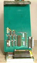
The Sun Remarketing SCSI card.
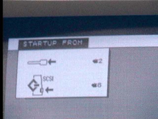
Startup from the SCSI card.
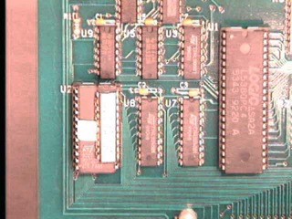
The QuickBoot ROM and PAL chip which allows for booting.
2. The original XLerator has an optional SCSI port. A cable provides a rear panel DB25 connector. Since this port is accessible at the full speed of the 16 MHz CPU, it is sometimes substantially faster than the expansion card SCSI port, depending on the drivers in use.
- The X/Lisa SCSI Accessories card provides additional features for use with the XLerator SCSI port
- internal 50 pin SCSI, 4 pin power and 2 pin fan connectors
- ROM to boot MacWorks Plus/II from a SCSI drive (subsequently available as QuickBoot for the Sun SCSI card)
- Some of these cards were sold with a hard-drive installed on the card.
In general, those SCSI devices that work with the Macintosh Plus will also work with a Lisa SCSI port running MacWorks Plus/II.
Potential Problems
- If an XLerator is installed, hard drives may not work with "blind" read/writes due to the increased speed (just as with a Mac Plus with an accelerator installed)
- Some later SCSI drivers require more space in the System Heap than is available in a machine with 2MB of RAM. Using 4 MB or switching to an older driver can alleviate this problem.
Specific unusual devices known to work:
- ScuzzyGraph (provides 8 colour display with extended desktop)
- Asante Mini EN/SC (ethernet adapter)
- Faralon EtherMac Microscsi (ethernet adapter)
- Dayna Port SCSI/Link-T (ethernet adapter)
Specific devices known to NOT work (although success may be possible with a particular driver version):
- GCC PLP II SCSI Laser Printer
- this printer relies on precise timing to scan properly
- PLI SuperFloppy aka TurboFloppy
- This 1.4MB HD floppy drive with SCSI interface includes a driver in its ROM. The driver uses a 68K TAS instruction, which is the only instruction that generates a read-modify-write cycle. The Lisa memory boards cannot perform this kind of cycle, so a crash or hang results. This drive does work if an XLerator is installed and turned on, as the XLerator RAM does support this kind of cycle.
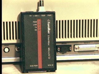
Faralon EtherMac Microscsi Ethernet Adapter.
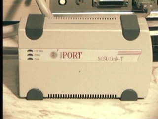
Dayna SCSI Port.
Note: The images on this page provided by http://lisa2.com , used with permission
�(Comment on this answer)
3.6.1. The floppy drive refuses to eject, or I can't insert a floppy in it. How do I repair it?
The likely cause is that there is some old dried up grease in the joints which prevent the ejection mechanism from functioning properly. This is a very common problem with the 400K Sony drives.Remove the Lisa's front case. Unscrew the drive cage nut. Carefully pull out the drive cage. There are cables that you can either leave hanging if you have a work surface nearby, or if you do not, you should unplug and remember the polarity of.
On my Lisa, the cable that comes from the motherboard and plugs into the LisaLite floppy adapter on the left hand side of the drive cage is not keyed. If yours is also not keyed, and you put this cable in backward later on, you'll short out the power supply and prevent the Lisa from powering on.
The floppy drive sits on four raiser posts. Unscrew these from the drive cage to remove it.
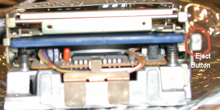
If there's a trapped floppy disk, press the eject button which is located to the right hand side of the drive.
Next, you'll need a junk floppy that you don't care about (one whose door is still functional and won't break inside your drive, or one that no longer has a door and spring), some WD40, paper towels, cotton swabs, and a tube of white lithium grease which you can find at hardware stores or some auto stores.
You should take the floppy outside, or at least in a well ventilated place (away from open flames of course) where you can safely spray the WD40 without getting it on furniture, etc.
Be careful to spray the WD40 at an angle, away from the center of the drive where the read/write head lives. WD40 on the R/W head is not a good idea. You're not trying to lubricate the drive, instead, you're using the WD40 to dissolve the old grease.
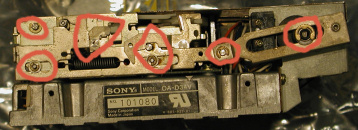
Insert the junk floppy and eject it repeatedly as you use paper towels and a few cotton swabs to wipe away the WD40 and old grease out of the joints. Next, apply a small amount of the lithium grease on a clean paper towel, and use a clean cotton swab to apply a small amount of the lithium grease on the joints circled in red. As before, insert and eject the junk floppy several times. As you do so, spread the lithium grease in exposed the areas of the joints.
When you're done, discard the cotton swabs, the junk floppy, and paper towels.
- If you have a floppy cleaning kit, then insert the drive back into your Lisa, reconnecting all the cables.
Get a floppy drive cleaning kit and clean the drive head. The easy way to do this is to power off any hard drive, and repeatedly attempt to boot from the floppy. This will spin the head cleaning floppy and clean the drive.
- If you don't have a floppy cleaning kit, unscrew the small round black screw on the back of the floppy drive. The cover hooks into the sides at the edges. Note how it fits in before you remove the cover.
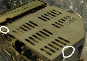
Remove the cover, exposing the drive read/write head.
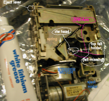
On a normal 400K floppy drive, the black plastic arm above the head has a small circular piece of felt (which applies pressure to the top side of the media, holding it against the head on the lower side). (As shown in some of the pictures, on my drive the bit of felt fell out a long time ago. However, some drives don't work properly if this pressure pad is missing.) This top part isn't part of the read/write head. The read/write head is underneath this. With a double sided 800KB drive, there are two read write heads (one on top, one on the bottom.)
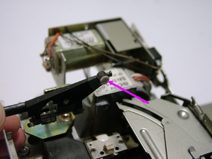
The above image better illustrates the top half of the drive arm being flexed upwards and shows the felt pressure pad. If yours is missing the felt pad, you'll need to fashion a replacement. (One person has made one out cotton swab tips, though this is not ideal.)
Using another clean cotton swab and isopropol alcohol, gently wipe the r/w head. You must be very gentle to avoid damaging the thin flexible metal head mount. Repeat cleaning the r/w head with a new clean cotton swab until you see no residue on it. Put the cover back on, replace the screw, then insert the drive into the drive cage, and into the Lisa, reconnecting all the cables.
Next replace the Lisa's face plate and power the Lisa back on.
If you didn't use a head cleaning kit, insert a blank disk and attempt to boot from it. The Lisa should eject this with an error.
Insert a boot disk, such as the one for MacWorks, and attempt to boot from it. This should work.
Sources: SunRem Do It yourself guide, James MacPhail - suggestion for using white lithium grease.
�(Comment on this answer)
3.7.1. How do I low level format my ProFile hard drive?
When installing an operating environment, such as the Lisa Office System or one of the MacWorks variants, all of the sectors of a ProFile/Widget hard disk are written with zeros before the actual file system structures are written to the disk.If this initialization fails consistently, it is possible that the drive is damaged and needs low-level formatting and/or further repair.
A low-level format is different from the normal initialization that installing an operating system on a ProFile or Widget does. During low level formatting, extra synchronization markers and track/sector ID's are written on the tracks in between the sector gaps to help the hard drive find the sector/track it's seeking.
In normal operation, this extra data is never written to. Over time, the strength of the magnetic signal of this data can fade, or is physically damaged as vibrations cause the r/w heads to smash into the platter.
When this happens, you get data errors. In cases where the damage is limited to only a few sectors, the hard drive can relocate a damaged sector to one of the spare sectors. ProFile drives have up to 32 spare sectors. Once they run out, any more damage results in symptoms such as loss of data and instability to the OS.
Should the first track be damaged, the OS will not be able to install and use the drive.
If using the OS installer to re-initialize/format the drive fails, the first level of service to address these issues is to do a low-level format. Unfortunately, in order to do this, you'll need an Apple /// computer with a ProFile interface card, the special low-level format ROM for the ProFile's Z8 processor, and the Apple /// ProFile formatting software to issue the commands. ProFile hard drives configured for normal operation do not have the firmware necessary to do low-level formats.
The technique, hardware, and software required to perform a low-level format of a Widget hard drive is unknown.
Low-level formatting cannot cure all problems, as damage to the disk surface or electronic failures may require replacement of some components. In short, for most of us, low-level formatting is just not possible. You're better off buying a replacement hard drive.
If someone out there has the right hardware to perform low-level formatting, please let us know if you'd be willing to perform this valuable service for the Lisa community.
�
(Comment on this answer)
3.7.2.1. At startup Lisa shows a hard drive error 81, what can I do?
This information is applicable to a Lisa 2/10 or Macintosh XL containing a 10MB internal Widget hard drive.
- error 81 is not exclusively caused by misadjustment/failure of the Widget brake, other problems can generate this error too, such as a bad cable/connection.
When the Lisa is turned on, the Widget drive will spin up and perform its own self-test. This happens independently of, and concurrently with, the Lisa's self-test. The Widget self-test and brake-release described below does not recur if the reset button is pressed; it occurs once at power-on only.
After the Widget spins up, the electric head brake releases with a distinct clunk or clack followed by the characteristic squeaking noise of the Widget head motor.
If the brake does not release, the Widget's self test won't complete successfully and the drive does not respond to the Lisa; the result is a cross over the internal drive icon with error code 81.
Without further information, many people assume that they need a whole new hard drive. Rather than spend the money, they shelve the computer. Well, it's time to dust it off! Error code 81 may simply mean the brake is out of adjustment. You can fix it, easily, in under an hour, with a #1 Phillips- head screwdriver and a .012 inch (0.3 mm) feeler gauge. Here's the complete procedure:
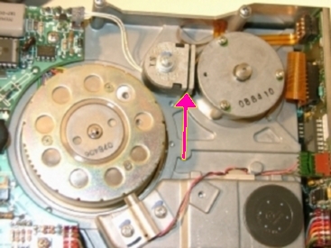
1. Disconnect the computer's power cord from the wall outlet. 2. Remove the disk-drive cage as shown in Figures 1 to 3. 3. Disconnect all data and power cables from the installed drives. 4. Turn the cage upside down. This puts the relatively light disk drive on top and the relatively heavy hard drive on the bottom.
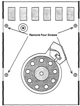
Figure 25 Four screws hold the Widget assembly to the sheet metal support bracket.
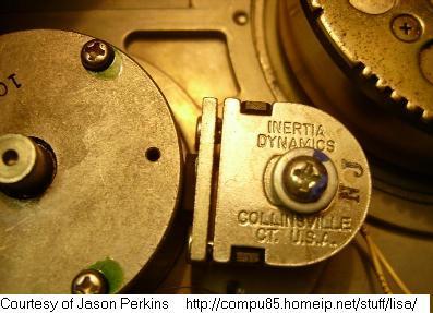
5. Use a #1 Phillips-head screwdriver to remove six screws (three on each side of the cage) which hold the hard drive in place. 6. Lift the drive cage straight up. This leaves the hard drive upside down on the table. 7. Use a #2 Phillips-head screwdriver to remove four screws from the sheet metal support bracket as shown in Figure 25. Lift the bracket away and put it aside. 8. Locate the solenoid marked "Inertia Dynamics, Collinsville, CT USA." Insert a 0.012-inch feeler gauge as shown in Figure 26.
Tighten the screw, reverse steps 7 through 1, and everything should be OK. If not, repeat steps 1 through 9, allowing a little more or a little less clearance, until you get the brake working.
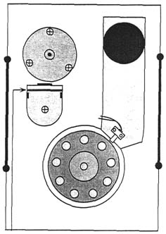
Figure 26 Adjust the brake gap (indicated by the arrow) with a 0.012-inch feeler gauge.
Actual photos of the drive mechanism (courtesy of JDM)
Closeup.
9. At the time of failure, clearance might be as much as 0.075 inch. Loosen the solenoid holding screw and adjust for 0.012-inch clearance.
Source: http://www.cs.dartmouth.edu/~woz/lisatech/page28_29.html ( Lisa/Macintosh XL Do-it-yourself Guide published by Sun Remarketing, Inc. )
Addendum JDM 2006-06-24
- In some cases, the Widget's brake does not release because the drive does not spin up. You may be able to get the drive to spin up by flipping the front side of the flywheel from right to left with the eraser end of a pencil. You have a few seconds after power-on or the Widget's self test will conclude it is not going to spin up to the correct speed and stop trying.
- If you are successful at starting your drive this way, backup your data immediately as it may not start again
Typical Widget self-test timing (seconds)
| 0 | Power-on | Waiting for platter spin-up |
| 10 | Spin-up complete | Waiting for brake release |
| 20 | Brake Release | Start fast surface scan |
| 28 | Fast scan complete | Start slow surface scan |
| 88 | Surface scan complete | Drive Ready |
�
(Comment on this answer)
3.7.2.2. My Profile or Widget drive shows error 84 (or another) on boot. How do I repair it?
An error while trying to startup from a hard drive may indicate a problem with the Lisa, the drive's hardware, or the data on the drive.The troubleshooting suggestions below assume the data on the drive is damaged. However, before assuming the worst, check the following:
- hard drive is properly connected
- hard drive data cable connectors are clean and straight
- Lisa is operating properly (self-test completes with no errors)
- ProFile drives will sometimes fail due to minor corrosion (and thus bad contact) in one or more of the IC sockets on the controller board (inside the ProFile). This can be cured by partially removing and re-installing the socketed chips. Do this one at a time to preserve the locations, and be sure to maintain the correct orientation.
If the Lisa configuration has been changed recently, or it has been out of use for an extended period, also check the power supply voltages at the drive.
If the problem persists, troubleshooting typically uses the following progression:
- attempt to repair the drive using the OS installer
- if repair fails, attempt to re-install the OS
- if OS installation fails, perform a low-level format
- if low-level formatting fails, repair the drive electronics and/or disk assembly
Double initialization for MacWorks
In response to some problems re-installing some early variants of MacWorks, Sun Remarketing had this advice (it may not be applicable to other OS installers):
Source: http://www.cs.dartmouth.edu/~woz/lisatech/page32_33.html ( Lisa/Macintosh XL Do-it-yourself Guide published by Sun Remarketing, Inc. )
Startup error code 84 pertains to Profile and Widget drives. It means the boot blocks are damaged. There are three possible fixes.
Fix one involves double-reformatting the drive-
first under Lisa OS, then under MacWorks XL. Double-reformatting the drive is time-consuming and it only applies to some computers. You can't use this method with a Macintosh XL Screen Modification Kit unless you pull the 3A ROMs and reinstall the old ROMs. Also, double-reformatting doesn't always work.
Editor's Notes: Not sure that this will help anything since it doesn't make sense
that one format will make a difference from another.  It might help if
you are using an old version of MacWorks, which sometimes gets confused
if you are installing it over a drive that has existing data.

If you have an Apple II or /// available, initializing the drive under ProDOS
or SOS may have the same effect as using LOS.
Fix two involves reformatting the drive with MacWorks Plus version 1.0. 18 or later. Holding down the Apple and the left Option keys while double clicking the MW Install icon opens the program in the expert mode. Expert mode recognizes most unmountable drives and gives the option to you to reinitialize them. Afterwards, the drive may or not be bootable.
Fix three is low-level formatting.
�(Comment on this answer)
3.7.3.1. What kind of cable should I use between the Lisa and my ProFile drive?
A straight through Male DB25 to Male DB25 cable is needed.Make sure that your cable has all the wires connected to all the pins. (There are DB25 serial cables that look identical, except, they only have a few of the pins wired - DO NOT USE THESE)
If you want to be absolutely sure, get a ohmmeter and check, pin by pin, that pin1 on one end matches pin1 on the other end. Repeat this for all pins and ensure there are no shorts between the pins.
Parallel Port cables and SCSI port cables have been known to work. You can make your own if you are patient.
The requirements are:
- Both ends are DB25 Male
- All pins are wired straight through (that is, pin 1 on one end is connected to pin 1 on the other end. Pin 2 on one end to pin 2 on the other, etc.)
- Pin #7 may need to be removed from one or both ends, as some Apple parallel ports have this pin blocked. If you are making your own cable, it is easiest to remove pin 7 from the connectors before you start assembly.
- The cable should not be very long, 35 inches (90 cm) is the recommended maximum.
You can use flat ribbon cable and crimp-on "IDC" connectors.
The original Apple cable is round with a silver/grey colour, and part number 590-0202-B moulded into the connector hoods.
�(Comment on this answer)
3.7.3.2. Where can I get a replacement ProFile or Widget Hard Drive?
Barring the very rare yard sale, or eBay finds, you're very unlikely to find a ProFile or Widget hard drive, much less one in working order.There are currently two modern replacements for these:
http://sigmasevensystems.com/xprofile The X/ProFile is a commercial replacement for the Lisa and Apple II or ///'s.
http://john.ccac.rwth-aachen.de:8000/patrick/idefile.htm IDE-File is a non-commercial project for Do it yourself'ers.
�(Comment on this answer)
3.7.3.3. My ProFile is very loud, how do I fix it?
The ProFile has no fan, so almost all noises are generated by the disk assembly.Usually the ProFile's "jet-engine" noise can be nearly eliminated by adjusting the static brush.
The static brush touches the bottom end of the spindle axle, and after some period of wear, can vibrate quite loudly.
If you (carefully) remove the hard disk assembly from the ProFile chassis, and remove the circuit board on the bottom, you will see the static brush. A small tweak sideways is usually all that is required to change the point of contact and stop the excessive noise.
Make sure that the brush is still making contact with the axle so that it can do its job, and do NOT "lubricate" the point of contact.
Source: James MacPhail / LisaList 2005.09.07
Larry Pina Recommendations
I've got 4 profiles. Of these 3 make the fridge compressor noise. They've all been alive for over 20 years now and still work. Granted, I rarely turn any of them on, and even then, only for a few hours, but they still work.
The Larry Pina book, Macintosh Hardware Repair Secrets describes how to fix this. It's a bit of a rare book to find, and usually around $30-$40, but it's worth getting. Chapter 13 of this book is what you're after:
"Some hard drives tend to be intermittently noisy, likely an annoying
loud refrigerator...  The fix is to remove the drive and check for a
static discharge button.  Intermittent strange noises often mean the
discharge piece is too close to the media.  Bend it back with a
soldering aid as shown in figure 13-29 and the noise will be gone.  Be
careful when you're doing this... Generally, all you have to do is
bend it back a little."
(The figure shows a soldering tool (the usual one with a blade on one end and a hook on the other you used to be able to find at Radio Shack) pointing to a circular knob in the middle of the board on the bottom of the hard drive.) It looks a bit like a spiral and is next to a crystal, a chip that has two large resistors under it, and below a large chip with a sticker on it. You can probably use long, a small head flat screwdriver instead.
I've not done this before, nor have I bent back the profile discharge tab - I don't mind the noise since I rarely turn the drives on.
Source: Ray Arachelian / LisaList 2006.05.11
Leave the ProFile powered for 3 days
Letting the hard drive run for three days on its side may heat the grease around the ballbearings and get rid of the noise.Source: Simon Claessen / LisaList 2006.05.12
NOTE: It's generally not a good idea to run a hard drive upside down, this may cause damage as the drive heads scratch into the surfaces of the platters. NEVER MOVE A HARD DRIVE THAT IS POWERED ON! Power it off first, wait until the platters stop spinning before repositioning it
�(Comment on this answer)
3.7.4.1. How do I replace a Widget Drive?
If you're actually lucky enough to find a spare widget drive and want to replace an old one, or just install a new one, these instructions may help:Tools and Parts: three hands, medium-shafted Philips-head screwdriver, film canisters.
Before you proceed, make sure that the Lisa is plugged in and that
(if the Widget is functional enough) you have booted the Lisa from
the hard disk at least once after plugging it in last! The Lisa stores
critical system parameters (time/date, device info) in two places:
the PRAM and the boot blocks of the boot disk. If the Lisa is unplugged,
the parameters in the RAM are lost and must be restored into RAM from the
boot disk. Installing a replacement Widget with no parameters in RAM may
cause incorrect information to be "restored" into parameter RAM. Incorrect
parameter info causes many system problems - be careful!
Step 1, Preparation: With the Lisa off, remove the front bezel by pushing up on the two tabs underneath, then pulling out. Loosen the finger screw beneath the floppy drive. Pull the entire drive assembly out of the cavity and rest it upon a clean, anti-static surface.
Step 2, Disconnect: Looking down upon the assembly from the front, remove carefully the three cables connecting the unit to the Lisa: the Widget power cable, the Widget data cable, and the floppy cable. Next, disconnect the two-lead fan cable attached to the top right of the uppermost board. Memorize how the fan wire snakes up around the Widget - you will need to know this later
Step 3, Detach: Gently lay the assembly on one side. Remove the two screws holding the Widget support plate in place in the aluminum rack and optionally place them in film canisters. Carefully turn the assembly over, taking care that the Widget does not shift. Remove the other two screws.
Step 4, Remove: Carefully set the assembly upright with a hand underneath the Widget to prevent it from shifting. Gently spread the aluminum cage, pulling the fan wire away from the Widget in order to avoid a tangle. Lift the Widget up and away from the cage and set it aside.
Step 5, Replace: Pull the fan wire taut and carefully spread the aluminum cage. Lower the new Widget into the proper position, while being careful not to tug or scrape the fan wire. Try to keep the wire from being squashed - remember how it was before you removed the old Widget.
Step 6, Cleanup: Replace the holding screws to secure the Widget in the cage. Reconnect the wires.
Step 7, End: Gently slide the cage back into the Lisa. Be very careful that the cables do not get caught on screws inside the case. Apple mentions this on the TIL, but I can't find it for the life of me! Replace the front bezel and power up the Lisa. If the Widget hasn't been used for a while, it may take a while before it actually starts to work! (or at least this is my experience)
Source: Tom Stepleton / http://web.archive.org/web/19980212223305/galena.tjs.org/~tom/service.html
�(Comment on this answer)
3.7.4.2. What does a working Widget Hard Drive sound like?
See this QuickTime movie of a working Widget startup sequence: http://lisafaq.sunder.net/movies/Widget.movThis view from the bottom of the Widget (while removed from the drive cage) shows the solenoid gap closing as the brake is released around 20 seconds into the sequence.
The squeaking noise during the surface scan is typical of the Widget's head seek motor.
The Lisa's self-test clicks and beeps are also audible. Note that the time it takes for the Lisa to do its self test varies with how much memory is installed (your Lisa self-test may be completed faster or slower).
�(Comment on this answer)
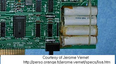
3.8.1. My Lisa has an I/O board that has a four pack of NiCAD AA batteries, what should I do?
You should immediately remove the batteries! If they haven't already leaked, you are very, very lucky. Most of these are very old and the batteries have leaked, usually damaging the board with corrosion!
There is little value to replacing these batteries with new ones, as good ones will only maintain the time for a few hours while the Lisa is unplugged. This is probably why the I/O board used in the Lisa 2/10 does not have backup batteries.
It is perfectly fine to run a Lisa without these batteries, all they do is maintain power to the floppy RAM (which contains the equivalent of the Mac's PRAM) and the real time clock in the COP421. This will be maintained just fine as long as the Lisa is plugged in to power, even though the Lisa is turned off.
That said, the real time clock may be useless as it's range is from 1980 to 1995 (unless you are using an updated version of MacWorks Plus II), and unless you are using your Lisa regularly, you are better off not leaving your Lisa plugged into power where it can be exposed to possible brown outs and power surges. You should also plug your Lisa into a very good power surge protection unit when using it, and leave it unplugged when not in use for an extended period.
More than likely, if you are reading this question, it's already too late and the NiCAD batteries have leaked. You have a few options. You can try to find a replacement I/O board, or attempt to repair your current I/O board.
I found the following web pages pages that address this type of repair. The last link in the list is a failed repair attempt. YMMV.
- http://www.rskey.org/calccorr.htm
- and http://www.flippers.com/images/GamePlan-Corrosion1.jpg
- http://oldcomputers.net/corrosion.html
Instead, try to clean up as much of the damage with an old toothbrush. Be careful not to breathe in any of the dust.
Look at the traces on the board, if any of them are damaged, you'll see a blueish green coating that's different from the board's own lacquer on the solder points, the traces may be raised up or puffed up, or even broken, you should clean the solder points between the traces, then reflow them using a soldering iron. After doing so, use an Ohm-meter, check for continuity.
If the resistance is still high (more than a few Ohms), solder another wire across the solder points of the traces to replace the corroded ones. Be careful not to cause a short circuit.
You may also have to replace any components damaged by the leak, and any damaged by short circuits caused by the leak. In my own case, I had to replace a VIA chip and a COP421 chip because the VIA chip had a bit of melted plastic. I replaced the COP421 chip because the mouse did not work on with this I/O board, but did with another.
COP421 chips are very difficult to find, their only sources are other Lisa I/O boards. According to the Lisa Hardware Guide there are identical COP421 chips inside the Lisa's keyboard, however, no keyboard that I've come across has these. Instead, they are Intel keyboard controller chips. If you have a dead, extra keyboard that has a COP421, you can try to swap the keyboard COP421 with the one on the I/O board. Please let me know if you find such a keyboard. I suspect these were only in the prototypes or very eary keyboards.
If you are able to locate a Mac XL I/O board (does not have an AM9512 socket, has a large IWM chip) and does not have NiCAD batteries or a switch, you can attempt to use this board. However, you'll also need a Lisa XL motherboard, and you should not use the LisaLite floppy adapter with it.
Addendum JDM 2006-06-10
I had suggested that Ray use diluted vinegar to remove the blue stuff on the basis of many well respected postings from a calculator site: http://www.hpmuseum.org.
My reasoning goes like this:
Apparently the leakage from NiCAD batteries is alkaline. A weak acid will help to neutralize this, whereas neutral water will only dilute it. Unless the leakage is neutralized, the corrosion will continue to spread.
The question is then, how does one remove or neutralize any remaining acid? After washing with water, I suggest using a circuit board flux remover, as they are designed for compatibility with circuit boards, and for removing acid residues of some soldering fluxes.
Flux remover comes in a range of formulas and strengths, I suggest one of the alcohol based formulas, as these tend to be safer to use on plastics and have low toxicity. In a pinch, 99% pure isopropyl alcohol (at your local pharmacy) can be used instead, but this may leave a white residue. Flux removers are available in pressurized cans that makes it easier to clean under components.
To avoid spreading the corrosion, hold the board with the battery corner down so that you don't need to wash more than necessary. Remove the solder from any joints that appear affected, and clean before resoldering. When cleaning, make sure you get under any ICs and resistors that are near the corrosion, as well as into any holes that go through the board.
I have used the above technique, and it appears to have been successful at stopping the corrosion.
�(Comment on this answer)
3.8.2. What's different on the Lisa 1 I/O board?
The Lisa 1 uses two 860KB 5.25" Twiggy drives instead of the Sony 3.5" 400K drives. When Apple provided the upgrade from Lisa 1 to Lisa 2, resistors R41 (3.3KOhm) and R47 (1KOhm) were cut on the I/O board, the I/O ROM was changed from version 40 to version 88.(Also, the two Twiggy drives were replaced by a single Sony 400K drive which interfaced with the LisaLite board, and the face plate was changed.)
�(Comment on this answer)
3.8.3. Will a Lisa 2/10 I/O board work in a Lisa 2/5?
It is sometimes desirable or necessary to use the I/O board from a Lisa 2/10 in a Lisa 2/5, often due to corrosion damage resulting from battery leakage. Although most of the I/O board works fine with a straight swap, the floppy disk does not. Hence some modifications are necessary to restore floppy disk functionality when a 2/10 I/O board is used in a 2/5 with a 3.5" floppy drive.Modifications
All of these modifications are performed on the Lite Adapter, located in the drive cage of the 2/5.
These modifications should be reversed to restore floppy drive functionality if a 2/5 I/O board is reinstalled.
- On the Component side
- - cut the trace from U2-6 to J1-20. This is the thin zig-zag trace which goes from U2 to J1, a suitable cut point is indicated by the red box in the picture of the component side below:
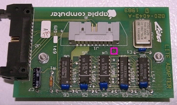
- On the Solder side
- - cut the trace between pins 14 and 20 of J2. This is the thin trace connecting two pins of J2, a suitable cut point is indicated by the red box in the picture of the solder side below:
- - add a jumper wire from J1-20 to U6-8. J1-20 is the pin closest to "1983", and pin 8 of U6 is the one connected to a thin straight trace; suitable connection points are indicated by yellow circles in the picture below.
- - add a jumper from J2-24 to ground (eg. to J2-13) pin 24 is second from the end farthest away from U2, and pin 13 is closest to, and in line with, J1; suitable connection points are indicated by blue circles in the picture below.
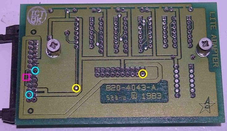
ROM Version
Since it programs the floppy drive controller, the I/O Board ROM must match the I/O Board, hence the 2/10 board should always have a rev 88 2/10 I/O board ROM (the 400k or 800k version to suit the floppy drive).
As a result, the Lisa will report that it is a 2/10 when a 2/10 I/O board is installed, regardless of any hard-drive attached. Although the icon changes, the parallel port hard drive is not influenced by the 2/5 or 2/10 designation except in the case of Xenix.
Background:
Lite Adapter
The Lite Adapter which is present in the drive cage of a 2/5 has two functions: modify the speed signal for the 400K drive, and re-map the 26 pin connector used by the twiggy drives to the 20 pin connector used by the 3.5" drives.
When the 2/10 I/O board is substituted, the correct speed signal is already generated by the I/O board, so the alterations made by the Lite Adapter interfere. However, the Lite Adapter is still required to re-map the connectors.
Motherboards and internal ribbon cable differences
The 2/5 and 2/10 motherboards are different, and require different internal cabling. If entire card cages are swapped, the floppy drive connectors are incorrectly wired, so the floppy drive will not work. The 2/10 internal parallel port will not work either. The keyboard and power switch are still correctly wired, so a cage swap can be used if the floppy drive and Widget are disconnected.
I/O Board differences
The main difference between the I/O boards is the floppy disk controller. The 2/5 board was designed for use with two 5.25" Twiggy drives, so implementing the 3.5" floppy required the addition of the Lite Adapter that is installed in the drive cage.
The 2/10 board was designed with a single 3.5" floppy in mind so no additional hardware is required. There is some evidence that it was designed to permit backwards compatibility with Twiggy drives. However, the ROM that would be required for Twiggy drives to work with a 2/10 I/O board is unknown.
Other minor differences are the battery and associated circuitry (missing on the 2/10 board), and the clock rate of the parallel port VIAs, which is nominally faster on the 2/10 board (1.25 MHz vs CPU clock/10). The stock CPU clock is 5MHz, so the VIAs in a 2/5 are nominally clocked at 500 KHz. However, when an original XLerator is installed in a 2/5, the VIA clock rate rises (ie. to 1.6 MHz with the 16 MHz XLerator), while the VIA clock rate in a 2/10 remains constant at 1.25 MHz. The clock rate of the VIA has a small effect on the speed of the parallel port, and may or may not affect the pitch of sounds generated by the speaker depending on the software in use.
Identification
One can identify the internal cabling as 2/5 by the two 26 pin ribbon cable connectors, while the 2/10 ribbon cable has one 26 pin connector and one 20 pin connector.
One can identify the motherboard of a 2/5 by the existence of a parallel port on the back panel, while a 2/10 motherboard has both interrupt and reset buttons but no parallel port on the back panel.
One can identify a 2/5 I/O board by the existence of two medium sized chips near the red ejector-latch, while the 2/10 I/O board has three medium sized chips near the red ejector-latch.
JDM 2009-05-05
�(Comment on this answer)
3.8.4.1. Why can't I set my Lisa's clock?
The COP421 controller, which keeps the Lisa's time, has a limitation of a single nibble (4 bit value ranging from 0 - 15) for the year. Since the Lisa was built in the 1980's, Apple used 1980 as the base year in the Lisa Office System, so the clock can only be set from 1980-1995.MacWorks Plus II originally used a base year of 1988, so the clock could be set between 1988 and 2003. A modification is available to change the base year as required.
The Lisa will maintain time only as long as it is plugged in. When unplugged, the time will be lost immediately (unless the I/O board has working batteries which will maintain the time for a few hours at most).
That said, please ensure that you have removed the 4-AA NiCAD battery pack from the I/O board of your Lisa. If your Lisa still has one that hasn't yet leaked, you're very lucky! Remove it ASAP! Do this right now! When it leaks, it will destroy your I/O board
�(Comment on this answer)
3.9.1. How do I repair my Lisa's keyboard?
Opening the keyboard case.
Flip the keyboard over, being careful not to push down on the keys. You might want to have another person help you, or use two sturdy cardboard boxes so that when you apply pressure on the screws, you don't harm the keys.
You'll see that there are five screws you'll need to unscrew. Two on the left, two on the right, and one on the bottom, under where the space bar is. Remove them, then carefully flip the keyboard right side up. The screws will fall out, don't lose them.
Gently remove the top cover. This will reveal the keyboard. You can lift this up and turn it over. This reveals a ground connection screw and a plug.
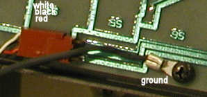
Gently remove the plug, then unscrew the ground wire, being careful not to lose the screw. You can now separate the keyboard from the bottom half of the case.
If you intended to wash your case, note that you cannot wash the bottom half of the case as
it is attached to the cable with no way to release it without damaging the cable.  Instead,
gently wipe the case with a paper towel.  Also, if you were to place the bottom half of the
keyboard into a dishwasher, you can expect to damage the serial number, and other stickers.
Gently blow away any dust between the keys. You can use your breath, or a small vacuum cleaner (be careful not to use one that's large enough to suck out the keys) stay away from compressed air as it can leak fluid into the keyboard, ruining it.
Check the coiled cable for breaks
Next, get an Ohm meter, set it on continuity and test the cable. All three wires should work, if they don't, you'll need to make your own cable, or find out where the break is. Sometimes, it'll be enough to wipe the grime off the phone plug.
The black ground wire that you unscrewed should map to the largest portion of the phone plug (the one farthest away from the tip.) The middle black wire on the inside brown connector jack should also map to ground.
The white wire should map to the middle of the phone plug.
The red wire should map to the tip of the phone plug.
The back of the PCB
Check the back of the printed circuit board. All the traces should be clean, no warping or scratches, and the solder points clear and shiny. If they're not, you might want to gently reflow the solder points. If you see warped, cracked, or cut traces, solder a wire across the solder points for that trace and glue the wire down to the PCB using a few drops of well placed hot melt glue. (Hot melt glue is reccomended because if you make a mistake, it can easily be removed without causing too much damage.)
If your keyboard works perfectly, stop here and reassemble it. If not, continue on with care.
Disassembling the key switches from the PCB
On the black metal tray, there are five screws. Two on the left hand side of the keyboard, one next to the left shift key, the other next to the ~ key. Another is above the 5 key. On the right hand side, to the right of the Numeric keypad, there's one screw next to the Enter key and another next to the * key. Unscrew these, but be careful not to put too much downward pressure as you can break off the keyboard connector plug if you do. It's best to do one side at a time with a cardboard box underneath the "ears" of the black metal tray so that you keep the plug safe.
Next, flip the keyboard over. There are numerous small screws throughout. Unscrew these taking care to not put pressure on the keyboard. These small screws are connected to the actual keyswitches - they're fairly easy to remove, but require extra care when you screw them back in.
Now gently remove the PCB from the metal keyboard tray.
The pads on the PCB should be clean. Don't touch the pads, but rather gently blow any dust away.
On the keyboard side, you'll see electrically non-conductive silver disks. Be careful not to damage these. Underneath them, there is a foam pad, and underneath them another disk.
Repairing the key switches
The Lisa keyboard's switches are not ordinary switches; they work by altering the capacitance between pads on the PCB using a non-conductive metallic looking foil disk (mylar?) on each key plunger. When a key is pressed, the foil presses against the pad (under the pressure of some foam material) which forms a capacitor; this is translated into an electrical impulse.
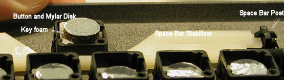
The soft foam deteriorates over the years and deforms. This is the usual cause of stuck, unresponsive, and poorly-working keys.
The Lisa uses a 3mm-4 mm thick foam material. This foam material is glued to a small round plastic disc on the key side which "snaps" inside the keyswitch plunger mechanism. On the circuit board side there is a special metallic appearing, but not electrically conductive foil.
Open the keyboard very carefully and reconstruct the key switches using new foam material. Don't forget to clean the pads on the PCB to remove the sticky glue and foam smudge. It is estimated that this will take a full afternoon, but once completed, you'll have a fully operational keyboard.
The circular disks that clip into the plungers can be popped out which makes it easier to remove the remnants of the old foam and attach new foam without contaminating the plunger mechanism.
Where you can, ecycle the existing foil pieces and reuse them. If you cannot, if the foil is worn out or destroyed, you can make new ones, but follow these instructions carefully:
Making your own foil disks
Take a sheet of aluminum foil, keeping it smooth and flat. Apply a single layer of Scotch tape on both sides of it. Cut out perfectly circular pieces, the same size as the ones in the keyboard. Use an Xacto knife or razor blade. Make sure you don't leave naked foil - you don't want the foil to cause a short circuit. It's important to cover both sides of the foil with tape so you have a surface that can be glued to the foam on one side and non-conductive on the other. The shape is important as this piece will act as a capacitor.
If possible, instead of foam, use double sided foam tape and cut this into a circular piece the same size as the disk. Since it's sticky, you won't need to use glue.
As a replacement for the glue don't use fluid glue, this may ruin your keyboard, instead use a sticky glue.
If you use cleaning fluids or canned air to clean the keyboard, you can easily damage it.
Don't use any of these to clean the keyboard!
You may find that if you make your own disks that they may not work on the first attempt. Just try again until you get the right shape, and right thickness of foam.
On some of the failed attempts, I've discovered a few keys that do nothing at all, and one that sent a whole bunch of keystrokes. (I used MacWorks's keycaps application to test the keyboard as it shows the key state for the entire keyboard.)
I suspect that the foam has little purpose. It helps push the foil against the pads to build the temporary capacitor, however, it's non reactive, so it's just there to absorb the force of your keypress and possibly prevent too much pressure on the capacitor.
Source: Ray Arachelian experimenting on keyboards, inspired by a post by Dr. Helmut Post on LisaList 2005.11.06 with help from James MacPhail.
Fixing the space bar
The space bar is a little more tricky. It's composed of several pieces. On the back of the keyboard (where the silver disks are) you'll find that there is a white bar. This white bar on the inside of the keyboard should be connected to two black plastic levers that also connect to the space bar on the left and right.
The parts of these that look like equal signs connect to the white bar. The parts of these that look like crosses connect to the space bar itself.
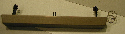
It is easier to connect the two black levers to the white bar before connecting them to the space bar. Do this first, but don't yet connect them to the space bar.
There is also a black plastic center piece that fits into the center of the space bar. Place the square portion of this part inside the space bar now, leaving the protruding bars that look like tongs on the outside.
There should be a spring on the outside of this shaft which lifts the space bar back up. Place the spring over the shaft before attempting to attach the space bar.
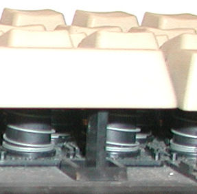
In my case, the two side levers on the left and right had popped off and fell into the keyboard, and the spring was nowhere to be found. I looked through my pile of junk hardware and found a similar spring that fit, however, it wasn't strong enough, so instead I used a piece of wire binding from spiral bound notebook. The space bar doesn't feel quite right, but it's functional. Alternatively, if you happen to have a dead Lisa keyboard that you cannot fix, you can scavenge springs from it.
If you put the space bar in backwards, it will rub against the bottom keys and won't fit, so be careful to note its slope and how it should fit. The sloped portion is away from the keys.
To join the left and right side levers to the space bar, it's easier to hold them down from the keyboard side (where they mate into the white bar on the inside.) Then gently push their cross portions into the space bar. After they're in all the way, push the space bar into the key shaft, this will cause it to mate with the button.
Put everything back together
When you're done, put everything back together. When you screw the keyboard back in, you should screw in the large alternate diagonal screws first. i.e. top left, bottom right, top right, bottom left. Then flip the keyboard over and screw in the smaller screws.
Protect your work
When storing or otherwise not using the keyboard, make sure the keys are protected so that they are not held down. If pressure is applied to the foam for a long time, it may lose its shape and resilience and need replacement again.
External Info
http://z13.invisionfree.com/OneTrueKeyboard/index.php?showtopic=35 Discovered on 2006.10.20 Contains more pictures of a take apart of a Lisa keyboard and the foam.
�(Comment on this answer)
3.10.1.1. How do I make floppy disks for use with my Lisa?

If you insert a Lisa disk into your Mac, it will not recognize it as having a valid file system and it will offer to format it for you. Formatting will wipe any data on the disk. Just because your Mac doesn't recognize the data on a floppy doesn't mean that there isn't any data there! It could be a Xenix, or Lisa Office System formatted disk! Make sure you know where it came from.
Also, you should not reuse Lisa disks as Mac disks. The 400K single sided drives the Lisa uses have a foam pad on the top where the drive head is, this may wear away the magnetic media on the top surface of the floppies, making them unreliable as double sided floppies.
Software Required
You'll need one of two applications. (Ideally you'll have both.) Apple's Disk Copy 4.2 program (later versions will not be useful) or Apple's DART program (version 1.5.4 was the last released).
Do not use later versions of Disk Copy, nor anything that comes with Mac OS X! These do not support the extra 12 bytes of tag data which is vital for use with your Lisa. Some of the later versions of Disk Copy claim to be able to convert DART disk images into Disk Copy images -
DO NOT USE THIS FEATURE
it will appear to work, but it will strip off the vital tag data, which will prevent the disks from booting on a Lisa!
Instead, obtain both the DART and Disk Copy 4.2 programs, since you may find disk images in either flavor when trying to locate software for your Lisa.
Between the two, when making your own disk images, you should use Disk Copy 4.2 as it's more compatible and friendly with your Mac and Lisa despite the fact that DART supports compression.
Hardware Required
An old Macintosh that has a floppy drive capable of using 400K or 800K floppies. Most older Macs will work, as will most early PowerPC's. (i.e. Mac IIcx, IIci, IIsi, Plus, SE, SE/30, PPC7100, etc. will all work, as will some early 68K and early PPC PowerBooks with floppy drives. A PowerMac G3 has been tested using Disk Copy 4.2 and it also works.) Those Mac clones that do not support 800K floppies will not work.
See addendum for some comments about preferred hardware and software.
Media
For Lisa disks (or 400K disks for use with MacWorks), you can use any 3.5" SS/DD floppies - that is single sided, double density. For 800K disks for use with MacWorks Plus/II, use DS/DD (Double sided, double density).
See addendum for some comments about re-using previously formatted floppies in a Lisa.
Reading the Data on a Mac
Your Lisa floppies will NOT be mountable for reading/writing as a file system in your modern Mac with the exception of floppies used with one of the varieties of MacWorks.
All the other Lisa file systems are not directly readable by a Mac, and the use of other tools (such as the terminal program) or the Lisa Migration Kit is needed.
Depending on your Macintosh hardware/software, you may be able to make images of your Lisa disks using DART or DiskCopy, and FEdit Plus and other software will allow reading/writing these disks at the byte level in hexadecimal or ASCII.
MacWorks XL
The System versions that run under MacWorks XL predate the HFS format, so all of the floppies used with this environment are in MFS format.
If you're trying to read/write an MFS floppy, older Mac OS's such as 6.0.8 will be able to mount it as "read only".
System 7 and above do not support reading of MFS floppies at all, inserting such a disk will invoke the "Do you want to initialize?" dialog.
MacWorks Plus and MacWorks Plus II
800K floppies used by MacWorks Plus/II are usually in HFS format, and can be read and written to by more recent Macintosh Systems than the MFS format.
Note that MacWorks Plus (1.1h and earlier) have a bug involving the detection of the HFS vs MFS floppy formats. MacWorks Plus assumes all 400K floppies are MFS, and all 800K floppies are HFS, which is not always correct. Although these are the default formats, the opposite can be invoked by holding down the option key while erasing/initializing the floppy. As a result, these non-standard floppies are not interchangeable between MacWorks Plus and other Macs, so any data on them should be copied to "normal" floppies. At least one commercial application was shipped on such a non-standard floppy, which would be corrupted when used with MacWorks Plus.
This bug was corrected in MacWorks Plus II (2.0 and up), which correctly identifies HFS/MFS floppies according to the initialization format rather than the size.
Making Disk Images
Simply launch either Apple Disk Copy 4.2 (preferred) or DART (not recommended if Disk Copy 4.2 is available) and select the options for making a disk image, then, when prompted insert the Lisa floppy. Once it's done, save the disk image to your Mac's hard drive.
Restoring Disk images
Launch Apple Disk Copy 4.2 (or DART 1.5.4), and load the disk image using the file menu (or button.) Then click on Make copy, and when prompted, insert a blank 3.5" floppy. DC42 or DART will format, then restore the data and verify it, and finally eject the floppy.
On Macintosh II and later computers, DART will make disks that will be marginal or impossible to read on Lisa hardware. In this case, duplicate the disk onto itself using Disk Copy 4.2 to convert the disk to the 5 bit-slip-FF format required by the Lisa hardware. See the section below on Preferred hardware and software for more information.
File Systems used by the Lisa
These depend on the operating system.
- MacWorks
- MFS
- HFS
- Xenix
- Monitor File System
- Lisa File System
- UniPlus Unix
Addendum JDM 2006-06-10, updated 2006-11-10
Preferred hardware and software for making floppies compatible with the Lisa
For trouble-free results, use another Lisa or a Macintosh 128K, 512K, 512KE, or Plus for making disks for use in a Lisa.
Although newer Macintosh models may appear to make disks usable on a Lisa, there are circumstances where some data will not be readable by Lisa hardware. In these cases, using DiskCopy 4.2 to duplicate the disk onto itself is likely to make the disk usable on a Lisa.
If you must use a Macintosh II or later, use:
- an 800K drive (instead of the 1.4M High Density SuperDrive)
- DiskCopy 4.2
- If the image is in DART format, make the disk with DART, then use DiskCopy 4.2 to duplicate the disk onto itself (this corrects the disk to have 5 bit-slip-FF's as required for the Lisa hardware)
To check whether a disk made in another machine is readable on a particular Lisa, mount the disk using FEdit Plus on the Lisa running under some (any) version of MacWorks and have it read every sector (eg. by searching for something, or put a weight on the mouse button). An I/O Error indicates some sector could not be read.
Technical Explanation: The Lisa floppy disk controller (FDC) anticipates 5 bytes of "bit-slip-FF" to synchronize its state machine to an address mark or data mark. The Macintosh FDC was improved to need only 3 bytes of bit-slip-FF, however use of this improvement was only implemented in the Macintosh II ROM and later.
The result is that some sectors of a disk written by a Mac II or later may not be readable by a stock Lisa FDC. This includes disks initialized on such a machine, as well as any file/directory data written on such a machine.
The rare exception is DiskCopy 4.2 which bypasses the floppy driver and accesses the floppy hardware directly. It happens that DiskCopy 4.2 writes 5 bit-slip-FF's even on hardware as recent as the beige G3 desktop, and regardless of whether the source disk/image used 3 or 5 bit-slip-FF's.
The number of bit-slip-FF bytes on a particular floppy can be determined using a PC with the Central Point "Deluxe Option Board", which has the capability of reading individual magnetic transitions on a disk.
For further information about bit-slip-FF bytes and the GCR encoding of Apple floppies of this era, see the Apple II book "Beneath Apple DOS".
MacWorks Plus II includes a Programmable Frequency Generator (PFG) that provides real-time adjustment of the FDC timing under software control, enabling MacWorks Plus II to read almost all Macintosh disks written with 3 bytes of bit-slip-FF.
Re-using floppies on a Lisa
The Lisa 2/10 aka Macintosh XL has a slightly different FDC than the earlier Lisa. One of the differences is that using an XL to re-initialize a previously formatted floppy almost always fails.
For best results with an XL, only new, uninitialized/unformatted floppies should be initialized. Previously used floppies should be re-initialized on another machine, or can be re-used by putting their contents in the trash.
Using a bulk eraser is an alternative when new floppies are unavailable.
�(Comment on this answer)
3.10.1.2. Where can I find 3.5" DS/DD Media for my Lisa?
The Apple Lisa 2 uses normal 3.5" Double Density (DD) floppies (not High Density HD 1.44MB)DD floppies and drives were originally available Single Sided (SS) and later, Double Sided (DD), which are still available (ca. 2006).
DS/DD floppies are commonly referred to as 720K due to their capacity when formatted on a PC MFM drive; the same DS/DD floppy will format to about 800K in a Macintosh with an 800K drive. Similarly, a 400K SS/DD disk may be labelled 360K.
- The 400K drives in stock Lisa 2 computers use only the bottom side of the floppy, so either SS or DS floppies can be used for those drives.
- If you have installed the 800K drive upgrade for use with MacWorks Plus/II, use DS/DD floppies if possible.
- When DS/DD floppies first became available, they were quite a bit more expensive than SS/DD floppies, so many people used SS/DD floppies in DS drives. This usually works fine, however there is a potential concern in that the second side of the SS floppy may have failed certification testing. There was also a rumour that the second side was not always polished, which may cause faster wearing of the upper head of a DS drive.
- In a pinch you might be able to cover the HD detection hole on a 1.44M floppy and try to use that, but it's best to locate DD floppies for your Lisa as the magnetic properties of HD and DD disks are different.
- Used floppies are plentiful and can be re-used. PC formatted floppies can be re-initialized for use on a Lisa. Note that the Lisa 2/10 will sometimes have problems re-initializing a previously initialized disk. See the section on making floppy disks from images for more information.
I'm not affiliated, associated, or even a customer of the following links. They came from froogle. YMMV. Caveat Emptor. If you find other sources, please let us know.
- Imation 12882 3.5 DS/DD Diskette 10 pack from ProVantage
- Imation 12042 - 3.5 Inch Diskette DS/DD Unformatted - 10 Pack from TheGraffixGuy
- Imation 12882 - 10-Pack 3.5in Diskettes, IBM Format - DS/DD The GraffixGuy
- various brands OldSoftware.com
(Comment on this answer)
3.10.2.1. What's known about Twiggy media?
Twiggy media are similar to 5.25" HD/DD floppies used on PC's, however, they have two windows in the casing where a read/write head can access the media.Semaphore Signal Issue 1 has the following to say about them:
Among the various innovations introduced by Apple in its Lisa product is yet another style of floppy disk. You won't yet find this particular disk on the shelves of many computer stores. The only name we've found for it so far is 687-8001 (the packing list entry for a box of five blank disks). The manuals don't say, but a source from Apple assures us that the edge notch not on the corner is the one for write protecting the disk.
You can find out more about Twiggy media (aka FileWare) here http://www.brouhaha.com/~eric/retrocomputing/lisa/twiggy.html
�(Comment on this answer)
3.11.1. How do I switch the power supply to work at 110V or 230V?
This is easily done with the datapower 1.8 Amp power supply. The 1.8A power supply has internal jumpers that are adjusted to suit the line voltage.
The jumpers connect spade connectors labelled E4 through E9, located to the immediate left of cr2 and the fuse.
The 110V configuration has the jumpers connected between E6-E7 and E8-E9 as shown in the image below, and between E4-E5 (not shown).
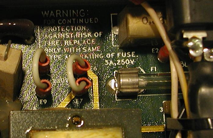
The 220V configuration has a jumper connected between E7-E8 as pictured below, and no jumper between E4-E5 (not shown):
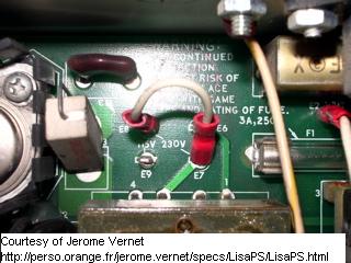
Switching the line voltage for the 1.2 Amp power supply is awkward as it involves soldered jumpers and changing the filament transformer used for the standby power.
�(Comment on this answer)
3.11.2. My Lisa doesn't power on and makes ticking sounds or whines when I press the power button. What is wrong?
This is a symptom of a short circuit, overload, or misadjustment of the power supply. Another behavior is that you press the power button, the light on the power button lights up for a short instant and then goes off, while the speaker makes ticking sounds.If you have just removed a load such as expansion or memory cards, or an internal hard disk, then the reduced load may be allowing the power supply voltage to rise too high, causing the over-voltage crowbar to activate.
If you have just added a load, the change in load may be overloading the power supply, or the new component may have a short circuit.
Locating a short circuit
Take out all the cards, one by one, examine them, make sure the contacts are clean.
If your Lisa has a LisaLite card between the Lisa motherboard and the floppy drives, disconnect it as well - it may be backwards.
You should be able to remove both memory boards, the CPU board, and any drives, leaving only the power supply, CRT+video card, and the I/O board and turn the Lisa on. If it does turn on, you have a short somewhere on one of the removed items. Shut the Lisa off, and one by one insert each card/device; turn the Lisa on each time to isolate the bad card/device.
If you are unable to resolve this, and have a spare power supply, and that power supply works, check the large diodes and capacitors in the nonfunctional power supply.
Adjusting the power supply
The Lisa power supply has an output voltage setting which may prevent startup when in need of adjustment, see the appropriately named section for details.
�(Comment on this answer)
3.11.3. How is the Lisa Power Supply Adjusted?
The Lisa switching power supply has a single voltage adjustment, which is accessed from the side of the PSU case closest to the card cage. Since this adjustment is not accessible while the PSU is installed, the usual technique is to make small adjustments iteratively until the output voltage is satisfactory. This control is moved counter-clockwise to increase the output voltage.The adjustment controls the +5 output primarily, with the other outputs tracking accordingly. In a situation where there is an unusual imbalance among the loading of the voltages (typically an internal hard disk that draws an unusual amount of current from the +12 supply), you may not be able to achieve satisfactory levels on both the +5 and +12 outputs. The usual solution is to upgrade to the larger capacity "DataPower" power supply (commonly referred to as the 1.8 Amp PSU due to its rating at 120V).
For optimal results, configure the Lisa as it will be used before adjusting the PSU, as adding memory, expansion cards, etc. will change the load and affect the voltage.
Increasing the voltage too much will trigger the over-voltage protection crowbar, causing the power supply to shut-down repeatedly (usually accompanied by a ticking sound). This symptom can also indicate a load that is too small or too large eg. a short-circuit.
�(Comment on this answer)
3.11.4. How do I check the voltages on my power supply?
The Lisa Power Supply is actually composed of two power supplies. The main power supply (switching power supply) is turned on by the COP421 controller on the I/O board. There is a secondary linear power supply that provides low power to the COP421 controller which is always on. They're both on the same circuit board inside the Power Supply unit.To measure voltages on the I/O board with the back panel removed, you will need to bypass the back panel safety interlock switch.
Whenever the power cord is plugged into the Lisa (and into a power outlet), the linear supply powers the COP421. If your Lisa doesn't do anything when you turn it on, test the voltage on this chip.
To check the standby power
The COP421 is CMOS and especially sensitive to ESD and brief short circuits. BE CAREFUL NOT TO SHORT THIS CHIP Due to it's fragile nature, you may want to investigate other causes before probing the COP421.
To avoid accidentally shorting adjacent pins on the COP421 while probing, disconnect the power cord (and turn off the I/O board battery if present), wait a few minutes for any stored power to discharge, secure your voltmeter leads, then connect the power cord to make your reading.
Measure the voltage on the COP421 chip (U9F on the I/O board). Pin 9 should read approximately 5V when the standby power is operating (Lisa plugged in and interlock switches engaged).
If pin 9 of the COP421 shows about 5V, and you still cannot turn on your Lisa, monitor pin 12 of U7F while you depress the power switch. If this signal changes state but the Lisa does not turn on, the switching power supply circuitry may be bad, or if you get no activity at all when you press the power switch, the COP421 or U7F may be bad.
To test the output voltages of the switching power supply
The chassis is connected to digital ground inside the power supply, but there are a couple of problems with using it to measure voltages accurately, most notably that it is not necessarily at exactly the same ground potential as the circuitry.
To make precise measurements, pick a ground on the circuit board itself. One near the source of power (the card edge) would be the best choice, as farther away may read at a slightly different potential.
A suitable location is the negative side of capacitor C47 or C50 on the I/O board.
You can access almost all of the voltages via the I/O board, which is relatively safe to do (no need to be near the high voltage in the power supply or video circuitry).
In particular, on the I/O board you can find:
- +12 at the positive side of capacitor C21
- - 5 at pin 8 of U10E (26LS30)
- - 12 at the negative side of capacitor C9
- +5 at the maximum pin number of most TTL ICs or the adjacent bypass capacitor
- +5-Standby ( ~5.7 V ) at the anode of diode D9 (present if Lisa is plugged in, even if turned off)
From the I/O board, you cannot access the +33 volts used by the analog video card, or the high voltages generated by it, but you can usually tell if the video card is working by the presence of something on the screen (even if it is random).
If you have an internal hard drive that is not working properly, checking the voltages at the hard drive would be appropriate as it may see lower voltages compared to those appearing at the I/O board. (Due to the higher current drawn by the hard drive, and the different wiring path.)
Source James MacPhail / LisaList 2006.04.25
If you have a Lisa 2/10, there is a power connector for the Widget hard disk in the drive cage area, which is a convenient place to check the +5, +12, and - 12 voltages:
| Black | Ground |
| Orange | + 5 |
| White/Orange | + 12 |
| White/Blue | - 12 |
| Green/Yellow | Power Good (open collector) |
Suggested by: Jason Perkins / LisaList 2006.04.25
�(Comment on this answer)
3.11.5. There is more than one kind of Lisa Power Supply, which one do I have?
The Lisa Power Supply Unit (PSU) is one of two kinds:
Original Apple PSU aka 1.2 Amp
This PSU is identified by one of the following rating labels beside the power cord connector:
- Units configured for North America
- Part number: 620-6103
- 120 VAC, 60 Hz, 1.2 Amp, 150 W
- Units configured for outside of North America
- Part number:
- 220-240 V~, 50 Hz, .7 A, 150 W
DataPower PSU aka 1.8 Amp
This PSU is identified by the following labels:
- Units configured for North America
- Part number: 699-0189
- 120 VAC, 60 Hz, 1.8 Amp, 150 W
- Units configured for outside of North America
- Part number: 699-0190
- 220-240 V~, 50 Hz, 1 A, 150 W
Notes
- The DataPower PSU can be switched between 120V and 220V by moving some internal jumpers.
- The Apple PSU can be switched between 120V and 220V by moving an internal jumper and replacing the standby power filament transformer with one of the appropriate voltage.
- The DataPower PSU was installed in the Lisa 2/10, as the extra load of the Widget is too much for the Apple PSU.
- The DataPower PSU is generally considered much more reliable and easier to repair than the original Apple design.
- Many Lisas had their power supply upgraded to the DataPower unit.
(Comment on this answer)
3.11.6. The light in my Lisa power switch has burned out, can I replace it?
Yes, the lightbulb in the power switch is inexpensive and can be replaced with minimal effort.
- Note that the lightbulbs are fragile; the filament will likely break if the bulb is dropped on a hard floor.
1. Locate a replacement bulb
- The bulb is "type 86" which is a T-1 3/4, 6.3V, 200mA, 20000 hour, wedge base incandescent bulb
- These bulbs are readily available (ca. 2006) from electronic parts distributors, such as DigiKey, Allied Electronics, etc.
2. Turn off the Lisa
- Unplug it if you don't mind losing the time and date
3. Remove the switch cap
- The cap has two detents, one on each of the top and bottom. Using a non-metallic tool such as a wooden tongue depressor (to prevent gouging the plastic), pry the cap off. You may need to pry both sides at once.
4. Remove the bulb
- With the cap removed, you can see a small metal ejector tab below the bulb. Pull on the ejector to remove the bulb.
5. Insert the new bulb, and replace the cap
- Note that when replacing the cap, you will press the power switch, so the Lisa will turn on (or off) if it is plugged in.
(Comment on this answer)
3.11.7. My Lisa power supply is bad, how do I repair it?
The most common failure points of the Lisa PSU are the capacitors.
DANGER: Replacing the capacitors in the power supply should be done only by those familiar with the risks, and able to solder. Because the PSU has large line-voltage capacitors, it poses very serious health hazards and even the danger of death by electrocution. If you're not comfortable with component level soldering, or don't want to risk damaging your Lisa, or possibly killing/electrocuting yourself, find a TV repair store and ask them to replace the capacitors for you.
As with most CRT/power supply repairs, the recommended course of action is to unplug the Lisa and pull out the power supply, then leave the power supply disconnected for a few days to allow the large capacitors to dissipate their charge. Do this even if your power supply is dead, it might be alive enough to store a charge in some of the capacitors. Before doing work on them, either work with one hand behind your back or discharge the capacitors by connecting a large resistor to their terminals. You could short them, but doing so may cause damage to the power supply.
With electronics of this age, mechanical problems are the most likely to occur. The second most likely thing to go wrong is that capacitors dry up over time, and some will actually burst and leak electrolytes on the boards, ruining them. Replacing them before they go bad with modern components is a very good idea. Be sure to purchase high quality capacitors from well respected sources such as DigiKey (Several years ago, there were a rash of knock-off capacitors that caused lots of PC motherboards to be destroyed.)
In my personal experience, I've had Lisa Power supplies die on me, and when I've taken them apart, I've found one of the smaller capacitors had exploded. Replacing it, along with replacing some of the larger ones repaired the power supply.
Before you attempt the repair, know whether you have a 1.2A or 1.8A power supply. You may need to obtain the schematics for that power supply so that you can identify the components and their values.
- Beware that some of the power supply capacitors are not polarized, such as the X2 line filter capacitors. i.e. they can handle AC voltage, and are safety rated for use "across the line." Make sure you don't replace them with polarized or unrated ones
- When replacing polarized capacitors, they must be put in the right way or they may explode.
You can replace existing caps with ones that will handle a little more voltage - this may help them last longer as well. i.e. replace the 2200uF 16V capacitors with 2200uF 25V ones. (Keep the uF values the same) In fact, you will probably find that you need to use a capacitor rated for a higher voltage to get one with the same lead spacing as the original one. If you have a choice between 85 and 105 degree temperature ratings, choose 105.
It's very difficult to find out if your capacitors are bad unless they're visibly damaged, and if they are, they're nowhere near spec. To test them you'd need ESR test equipment and you'd need to desolder the capacitor you suspect in order to test it. It's about the same amount of work to replace it, and capacitors aren't all that expensive (unless you want to replace all of them).
It is typical to find the two large rectifier filter capacitors are failing due to the higher voltage (~200V or more depending on the type of PSU). Inspect them visually. If you see any warping, or expanding, or what look like bubbles from the side or top, replace them. In some cases, the damage isn't obvious until the capacitor is removed from the board. Since capacitors from the same manufacturer will tend to age at the same rate, if you find one that is bad, you should replace the others of the same size together.
If you see what look like clear plastic square capacitors with an amber tint, look carefully at them. When they age, you'll see cracks forming on their sides, like little lines. If you do see this, replace them immediately, they're about to explode. (Not to be too dramatic here, but they won't do anything more than harm your power supply, however, with Lisas being rare, and replacement parts becoming less available over time, you'll want to preserve your hardware.)
�(Comment on this answer)
3.12.1. How should I set the Apple Daisy Wheel Printer DIP switches?
ADWP - Apple Daisy Wheel Printer known wheels:Daisy Wheel Printer DIP switch should be set as follows:
DIP Switch 1
| 1 | closed |
| 2 | closed |
| 3 | closed |
| 4 | OPEN |
| 5 | OPEN |
| 6 | closed |
| 7 | closed |
| 8 | closed |
Source: Lisa Owner's Guide
�(Comment on this answer)
3.12.2. What Apple Daisy Wheel Printer font wheels were available?
The following font wheels are known to have existed:
- Courier 10
- Prestige Elite 12
- Gothic 15
- Executive PS
- Modern P5 Plus Italics (Lacks " @ % { } < > \ characters)
- Modern 10/12/P5
- Modern 10/12 plus Additional Characters
Source: Lisa Owner's Guide
�(Comment on this answer)
3.12.3. How should I set my ImageWriter dip switches?
ImageWriter:Dip Switch 1:
| 1-1 | Open |
| 1-2 | Open |
| 1-3 | Open |
| 1-4 | Open |
| 1-5 | Open |
| 1-6 | Closed |
| 1-7 | Open |
| 1-8 | Open |
Dip Switch 2:
| 2-1 | Closed |
| 2-2 | Closed |
| 2-3 | Open |
| 2-4 | Open |
Source: Lisa Owner's Guide
�(Comment on this answer)
3.12.4. What printers can I use with my Lisa?
The Apple Lisa supported the following printers:
- ADMP (Apple Dot Matrix Printer) - this is a parallel printer identical to the ImageWriter, but connects to a Parallel Port instead. It is recommended that you connect it to a dual parallel card instead of the motherboard parallel port.
- ImageWriter - connect this to Serial port B
- Apple Daisywheel printer
- Canon Inkjet - This was the only color printer the Lisa supported
Other printers are supported via MacWorks (over AppleTalk, or otherwise) or Xenix.
�(Comment on this answer)
3.13.1. How can I connect my Lisa to an AppleTalk network?
The MacWorks variants support AppleTalk (later renamed LocalTalk/EtherTalk to differentiate the physical layer from the software layer). If you are using MacWorks is well worth the small effort to get it working.Since it takes a long time to make, read, and swap floppies, AppleTalk is a great way to move software to a Lisa running MacWorks. eg. Installing System 7 is much easier if you install a minimum System 6 with AppleShare client from floppies, then use AppleTalk to mount and run the System 7 Network Install from another Mac (or copy the System 7 installer images to the Lisa for use with a disk image mounter).
The other Lisa environments do not support AppleTalk. There was an "AppleNet" card for the Lisa, but it did not reach commercial distribution; it was the predecessor to AppleTalk.
Original AppleTalk
The original AppleTalk cabling system was later renamed LocalTalk. Farallon made a similar system named PhoneNet, which can be used instead.
The Lisa's Serial B port supports the differential transmit/receive signals required for AppleTalk.
Apple sold an AppleTalk connector kit with a DB25 connector for use with the Lisa, however these are rare. You can make a DB25 adapter to use an AppleTalk connector that has a Macintosh DE9 or Macintosh Plus MiniDIN connector on your Lisa.
Equivalent Pins for LocalTalk cabling
| Signal | DB25 | DE9 | MiniDIN 8 |
| TxD - | 2 | 5 | 3 |
| RxD - | 3 | 9 | 5 |
| RxD + | 19 | 8 | 8 |
| TxD + | 20 | 4 | 6 |
| GND | 7 | 1, 3 | 4 |
If you don't have any LocalTalk/PhoneNet transformer boxes, you can make a two computer network by connecting TxD+ on computer A to RxD+ on Computer B, etc.
AppleTalk over Ethernet
If you have a SCSI interface, you can use one of the SCSI-Ethernet adapters. Asante and Farallon adapters have been found to work, others will probably work too if they are compatible with the Macintosh Plus.
�(Comment on this answer)
3.14.1. What do the error beeps mean?
| Tones | Meaning |
| lo | CPU board or Memory error |
| lo, lo | Memory failure (no usable memory) |
| lo, hi | Card Cage error (general logic failure) |
| lo, lo, hi | CPU board error |
| lo, hi, lo | I/O board error |
| lo, hi, hi | Memory error |
| hi, lo, lo | Expansion slot error |
| hi, lo, hi | Keyboard error |
| hi, hi, lo | Keyboard/mouse disconnected |
| hi, hi, hi | Startup device invalid/failure |
| click | Basic test passed |
| click, click | Self-test completed |
| hi | Keypress ignored |
The triple tones are typically displayed with an icon that indicates the source of the problem, but of course, in the case of some CPU, memory, or I/O board errors, the display will be either dark, random, or flashing.
Source: Lisa ROM, Lisa User's Guide
�(Comment on this answer)
3.14.2. I got an error from the POST ROM, what does it mean?
| Code | Icon | Symptom | Possible cause or solution |
| 23 | Diskette | Unreadable diskette | Reformat disk |
| 38 | Diskette | No startup file on diskette | Install system |
| 39 | Diskette | Drive ROM can't keep up | Wrong drive ROM (or 800K drive on 400K I/O board) |
| 40 | CPU card | Memory management problem | |
| 41 | CPU card | Selection logic problem | |
| 42 | CPU card | Video circuit problem | |
| 43 | CPU card | Parity circuit problem | |
| 44 | Lisa | Unexpected NMI interrupt | |
| 45 | Lisa | Bus error | |
| 46 | Lisa | Address error | |
| 47 | Lisa | Unexpected exception | |
| 48 | Lisa | Illegal instruction | |
| 49 | Lisa | Line 1010 or 1111 trap | |
| 50 | I/0 board | Keyboard VIA error | 6522A chip? |
| 51 | I/0 board | Parallel VIA error | 6522A chip? |
| 52 | I/0 board | I/0 COP421 error | COP421 chip? |
| 53 | I/0 board | Keyboard COP421 error | COP421 chip? |
| 54 | I/0 board | Clock error | |
| 55 | I/0 board | Serial port A problem | Z8530 chip? |
| 56 | I/0 board | Serial port B problem | Z8530 chip? |
| 57 | I/0 board | Disk controller problem | Lite Adapter? |
| 58 | I/0 board | I/0 board access error | |
| 59 | I/0 board | I/0 COP421 error | |
| 60 | I/0 board | I/0 or keyboard error | |
| 70 | Memory board | Read/write error | |
| 71 | Memory board | Parity error | |
| 75 | Internal HD | System files are damaged | Reinstall System |
| 75 | External HD | System files are damaged | Reinstall System |
| 75 | Floppy disk | System files are damaged | Reinstall System |
| 75 | Expansion card | System files are damaged | Reinstall System |
| 80 | Internal HD | Drive cable is disconnected | Check cable |
| 80 | External HD | Drive cable is disconnected | Check cable |
| 81 | Internal HD | No response from drive | Adjust solenoid? |
| 81 | External HD | No response from drive | |
| 82 | Internal HD | Drive doesn't answer | |
| 82 | External HD | Drive doesn't answer | |
| 83 | Internal HD | Other drive problem | |
| 83 | External HD | Other drive problem | |
| 84 | Internal HD | Boot blocks are damaged | |
| 84 | External HD | Boot blocks are damaged | |
| 85 | Internal HD | Drive can't keep up | |
| 85 | External HD | Drive can't keep up | |
| 90 | Expansion card | No card in that slot | |
| 91 | Expansion card | Can't start from that card | |
| 92 | Expansion card | Problem with the card ROM | |
| 93 | Expansion card | Other card problem |
Source: Larry Pina's Macintosh Repair & Upgrade Secrets quoted from http://www.mjposner.com lisa book
�(Comment on this answer)
3.14.3. What are the Apple shortcut keys in the Lisa Boot ROM?
If the Lisa's parameter memory is valid, and a default startup drive preference has been set, the Lisa will attempt to boot off that drive. Later revision ROMs will attempt to boot from the built-in parallel port if the parameter memory is invalid.You can prevent the Lisa from automatically starting up by not powering on the ProFile hard drive on a Lisa 2/5, or pressing any key other than the CapsLock key after the first click that you hear.
Hold Apple and press one of:
| 1 | Upper Twiggy drive on Lisa 1, or Widget Hard Drive on 2/10 |
| 2 | Lower Twiggy or 3.5" Floppy Drive |
| 3 | Built-in parallel port (external ProFile, or internal Widget) |
| 4 | Slot 1 lower connector |
| 5 | Slot 1 upper connector |
| 6 | Slot 2 lower connector |
| 7 | Slot 2 upper connector |
| 8 | Slot 3 lower connector |
| 9 | Slot 3 upper connector |
The upper/lower nomenclature is applicable to the Dual Parallel Port card.
For some expansion card ROMs (eg. QuickBoot, LSAC), upper/lower is a misnomer. In this case, the lower number invokes normal startup, while the higher number may be an alternate (eg. in the case of QuickBoot and LSAC in a machine with two SCSI ports: "use the other SCSI port").
Other keys:
Apple and Enter (on keypad) aborts boot. Apple and Shift P - aborts boot, do power cycling.
Source: Lisa Owner's Guide and ROM source
�(Comment on this answer)
3.14.4. How do I enter Service Mode in the Lisa's ROM?
Turn on your Lisa. During the self-test (but after the first "click"), press the Spacebar. When you reach the "Startup From" menu, select a nonexistent volume (such as the floppy drive). When it gives you the error message, press Apple-S. You should then be in Service Mode.Source: http://web.archive.org/web/19980110152041/galena.tjs.org/~tom/saq.html
�(Comment on this answer)
3.14.5. What ROM versions are there?
First, you should know that there are two different ROM's in the Lisa. One is the CPU board ROM whose version is designated by either a single letter (A-H), or 3A. The I/O board ROM version is designated by two HEX digits.The Lisa self test that occurs automatically when it is turned on or reset, displays the ROM version at the top-right of the screen. For example, if you see H/A8: H refers to CPU board ROM version 2.48 (48 is the ascii value of H, the 2 refers to Lisa 2.) The I/O board ROM version is A8.
For example:  The 3A refers to the CPU ROM with a screen modification, the A8 is the I/O ROM version.
Known CPU board ROM versions:
- 3A - indicates a screen modification kit has been installed for use with MacWorks. Also, the Lisa Video state ROM has been changed for the new video timing, and (usually) a transformer has been installed between the video board and the CRT. 3A ROMs will not work with Lisa Office System, Workshop, Xenix, etc. Part Number: 341-0346A and 341-0347A
- H - the latest ROM for Lisa Office System. Also compatible with MacWorks and Xenix. Part Number: 341-0175H and 341-0176H
- G - Very Rare - development only? Part Number: 341-0175G and 341-0176G
- F - Early Lisa 2 ROM for Lisa Office System. Also compatible with MacWorks and Xenix. 341-0175F and 341-0176F
- E - Very rare - development only Part Number: 341-0175E and 341-0176E
- D - somewhat common, might work with both 3.5" floppy as well as Twiggies Part Number: 341-0175D and 341-0176D
- C - Lisa 1 ROM (rare) Part Number: 341-0175C and 341-0176C
- B - Lisa 1 ROM (very rare) - development only? Part Number: 341-0175B and 341-0176B
- A - Lisa 1 ROM (very rare) - development only? Part Number: 341-0175A and 341-0176A
Known I/O board ROM versions:
- A8 - Lisa 2 Part Number: 341-0290B
- 88 - Lisa 2/10 Part Number: 341-0261D
- 40 - Lisa 1 - for use with Twiggies (very rare) Part Number: unknown
The I/O board ROM contains the instructions for the 6504 Floppy Disk Controller. Part of the static RAM used by the FDC is also used for storing preference settings while the computer is off. Otherwise, the I/O Board ROM is not involved with the many functions of the I/O Board.
Note that the version numbers may be misleading as various modifications exist, for example to allow the use of 800K floppies with MacWorks. (If you have details about these, please let us know so we can edit this answer.)
It is common for software to detect the type of hardware available by examining the I/O board ROM version
- The Lisa 1 and Lisa 2 used the original Lisa I/O boards and are the same except for the ROM and a couple of minor changes (clipped resistors)
- The Lisa 2/10 I/O board is somewhat different in that the VIAs are clocked at a higher rate, there is no battery backup, the AM9512 math processor socket is replaced by a WD2001 socket, and the Floppy Disk Controller uses an Integrated Woz Machine instead of a discrete state machine.
The Video State Machine PROM
There are two flavors of these, one for normal Lisas and another for Lisas with the screen modification (always paired with the 3A CPU ROM.) The first version of the PROM is unique to each Lisa (aside from duplicated PROMs), because it contains that Lisa's serial number.
During installation, the Lisa's serial number is written to each copy of the Lisa Office System installation disks, as well as the tool installation disks (i.e. Write, List, Graph, Project, etc.) so they can only be used with the Lisa they were originally installed on.
Symptoms of serialized disks are that you cannot install the disks on another Lisa, and you cannot print if the serial # on the install OS does not match that of the one on your Lisa's CPU board. Instructions for deserializing the LOS floppies using FEdit are on the internet.
The screen modification kit PROMs do not have unique serial numbers. However, you cannot use the Lisa Office System with the screen modification kit. Only MacWorks Plus/II and the appropriate variant of MacWorks XL 3.0 will work with the screen modification kit installed.
Common/Recommended combinations:
- H/A8 - Typical for a Lisa 2 or 2/5
- H/88 - Typical for a Lisa 2/10 or Macinstosh XL without screen modification kit
- 3A/A8 - Lisa 2 or 2/5 with screen modification kit
- 3A/88 - Macintosh XL with screen modification kit
- D/40 - Lisa 1 with Twiggy Drives
Duplicating Lisa ROMs
The CPU board ROM is actually a pair of 2764 (8Kx8) EPROMs, which provide 8K x 16 bits for the CPU.
The I/O board ROM is a single 2732 (2Kx8) EPROM.
The video state machine PROM is a 256 x 8 bipolar PROM with tri-state outputs eg. MMI 6309-J.
�(Comment on this answer)
3.15.1. The self-test fails at the memory board icon and reports Error 70 or 71, can it be fixed?
The Lisa's power-on self-test checks the RAM relatively thoroughly. In addition to reporting Error 70 or 71, it also attempts to provide information for repairing memory boards, so yes, repairing a memory board is often possible without a huge effort.However, before embarking on an effort to repair a memory board, ensure it is truly the memory board that is the problem. A poor connection at the card-edge connector of the CPU board or Memory board can be the cause of errors 70 and 71 (as well as many other error codes). Clean the card-edge connectors (see lisafaq-hw_general_tests.html) and swap around and in/out your memory boards to be sure a particular memory board has a problem.
During the self test, the results of the memory test are stored in some low memory locations (accessible from service mode). Using this information, it is often possible to localize a memory error to a single chip (designated by a row letter and column number), and with some desoldering expertise, the bad chip can be replaced and the memory board repaired.
The low memory locations of the memory test data begin at address $186. There are 16 words of memory bit error information; these 16 words correspond to the sixteen 128K blocks in the 2MB RAM address space.
An examination of the Apple 512K RAM board reveals the memory chips are configured in an array of 4 rows, labelled B,C,D,E and 18 columns (arranged as two groups), labelled 1-9 and 14-22.
Apple 512K memory boards have 4 rows of chips, each row being 128K. This means that 4 of the 16 test result words will exactly correspond to the 4 rows of a single 512K memory board... ie. one word per row.
Each 16 bit word contains bad bit information... a bad data bit is reported by the corresponding bit set to 1 in the word corresponding to the 128K memory block where it was found.
Columns
It is easy to associate the bad data bits with the coordinates of a column of 4 chips on the memory board; from the schematic: bit 0 is column 22, bit 7 is column 15, bit 8 is column 1 and bit 15 is column 8.
If there is just one bit set (ie. only one bad chip in a 128K block/row), then there are 16 possible values for the word, which map to memory board columns as follows:
  Word  Bit# = Column
  0001   0   =  22
  0002   1   =  21
  0004   2   =  20
  0008   3   =  19
  0010   4   =  18
  0020   5   =  17
  0040   6   =  16
  0080   7   =  15
  0100   8   =   1
  0200   9   =   2
  0400  10   =   3
  0800  11   =   4
  1000  12   =   5
  2000  13   =   6
  4000  14   =   7
  8000  15   =   8
If there is more than one bad chip in a 128K block, there will be more than one bit set and you'd get a character other than 1,2,4,8, or more than one non-zero character in the word.
Rows
The rows of 128K are designated B, C, D, and E by the coordinates on the board. However there is a complication or two...
The 16 words in memory are arranged according to logical address, not physical address, and it is, of course, a physical chip we're looking for. The complication is that the physical rows are mapped to logical addresses in a different order depending on which slot the board is in.
If you have one 512K memory board, regardless of which slot it is in, it will always be associated with the first 4 words... $186 - $18C.
If you have two 512K memory boards, the first 4 words are associated with slot MEM 2, and the next 4 words are associated with slot MEM 1.
The last 8 words are never used with 512K memory boards, since they correspond to the second MB of the logical address space. They would be used if you have more than 1MB of memory.
The four rows of the memory board are always mapped in BCDE or EDCB order (depends on the slot), so you can be confident that a single bit error maps to one of two rows... if the error is in the first or last of four words, then the problem is row B or E. If the error is in the second or third word, then the problem is C or D.
To figure out which of the two rows is the problem, you can read-up on the physical-logical address mapping scheme in the Lisa Hardware Reference Manual, and cross-reference that through the schematic to determine which physical row is going to correspond to which logical address block.
Or you can use a rule of thumb determined by observation...
It has been observed that for slot MEM 1, the order is BCDE, and for slot MEM 2, the order is EDCB.
The rows corresponding to the first 8 words starting at $186 are used as follows:
1 board in slot MEM 1
B C D E x x x x1 board in slot MEM 2
E D C B x x x x2 boards
  MEM 2     MEM 1
  E D C B   B C D E
Examples
A. 1 RAM board installed, error reported in first 4 words...
- 0000 4000 0000 0000
- error in bit 14 which is column 7
- if the board is in MEM 2, the second word corresponds to Row D
- if the board is in MEM 1, the second word corresponds to Row C
B. Error in second 4 words...
- 0000 0000 0000 0000 0020 0000 0000 0000
- this might happen if you have 1MB of RAM - 2 boards
- error in bit 5 which is column 17
- the second 4 words corresponds to MEM 1 when 2 boards are present
- the first word (of the second 4) corresponds to Row B of MEM 1
Parity Error 71
You may have noticed something missing... there are 18 columns of chips, not 16. The extra 2 are for parity bits, one for each byte.
If there was a parity error, then all the data bits might be clean, represented by 0 in all 8 words at $186. In this case, you will get error 71 instead of 70 from the memory test.
In the case of a parity error:
- one byte at $27C contains a number that corresponds to the row as follows:
  00 = row B when the problem board is in MEM 1, with MEM2 empty
  01 = row C when the problem board is in MEM 1
  02 = row D when the problem board is in MEM 1
  03 = row E when the problem board is in MEM 1

  04 = row B when the problem board is in MEM 1, with 512K in MEM2
  05 = row C when the problem board is in MEM 1
  06 = row D when the problem board is in MEM 1
  07 = row E when the problem board is in MEM 1

  00 = row E when the problem board is in MEM 2, regardless of MEM1
  01 = row D when the problem board is in MEM 2
  02 = row C when the problem board is in MEM 2
  03 = row B when the problem board is in MEM 2
- one byte at $27D contains $09 or $14, which correspond directly to the board coordinate column of the bad parity chip, column 9 or 14. If this byte is zero, exit service mode by typing 7, then type apple-1 to run the self-test again; it seems that sometimes this is necessary to obtain the parity error data.
- long word $270 contains the logical address where the error occurred
Miscellaneous
- To enter service mode, type Apple-S after the memory error is reported
- To display the 16 words at $186 type: 1186 20<return>
- To display 8 words beginning at $27C type: 127C<return><return>
- If your memory board has a serious problem in Row B or E, then the Lisa might not work at all, since it needs some working memory to do the self-test. In this case, try moving the board to the other slot, and/or add a good board in the other slot. These will change the logical address of the bad row and may allow the Lisa to work well enough to perform the self-test.
- This information applies to the long test. There is a short test that is performed after a warm reset; I believe it consolidates all the bit errors into the one word at $186, ie. the row(s) are not decoded. To make sure you are getting the long test, first turn off the Lisa, and if you have batteries on your I/O board, turn off the switch (and check the FAQ about removing the batteries to prevent corrosion damage).
- This information is specific to the 512K Apple memory boards. If you have a different memory board you'll still get the error results, but mapping them to a physical chip is not addressed here.
(Comment on this answer)
3.15.2. How do I tell how much memory my Lisa has?
You can use the Service Mode built-in to the ROMs to check the memory size, and do your own read/write tests to confirm it (although the self-test checks it pretty thoroughly).To enter Service Mode:
- press the space bar during the self test
- "Startup From" the floppy drive (with no floppy inserted)
- When you get the "no floppy" error, type Apple-S
The amount of memory is at location 2A8, so type this to see it:
  12a8[return]
  1[return]
The first two words of the data are the memory size in bytes, as shown below. Note that unlike intel chips, the 68K is big-endian; the high byte comes first.
| 512K | 0008 0000 |
| 1M | 0010 0000 |
| 1.5M | 0018 0000 |
| 2M | 0020 0000 |
| 4M | 0040 0000 |
More than 2MB is only possible with revision 3A ROMs, and CPU and memory board modifications.
Source: James MacPhail / LisaList 2006.06.26
�(Comment on this answer)
3.16.1. My Lisa's video display is unstable, how do I fix it?
My Lisa seems to be having a problem with its video. When I power it up, it boots properly but the video jumps a lot. For example, the vertical height of the image may jump between normal size and very narrow with a large black border, or the video will roll like an old TV with the vertical hold misadjusted. When I first got the Lisa everything was fine but it's been moved around some and I think it might've jostled the video adjustments.Original source of question: Clinton Yelvington / LisaList 2005.05.26
Answers:
A1
Try some contact cleaner on the pots at the top of the video board. HAVE THE SYSTEM OFF AND UNPLUGGED over night. High voltage danger!
First use a marker to mark where they are set.
Spray the pots with the contact cleaner then adjust them back and forth. Because you marked where they were set, you can put them back.
Answer Source: Jason Perkins / LisaList 2005.05.27
A2
If the monitor's height jumps flickering, it possible will be a dirty pot on the video board. If I remember right it must be one of the two in the center of the six pots top on the board or the right one. Just try to adjust the a little and see, what happens. But beware of high voltage near the tube !! Or check the correct connection of the plug from the board to the tube deflection unit (sometimes the plugs connection to the board is faulty too)
OR
if the height slides slowly from min. to max. and back again, then this could be wrong. Take a look at a vertical mounted coil in the center of the video board. I have seen several Lisas with overheated coils for deflection. Some of them were no more coils they have been a chaotic ball of wire, because the coils core has melted. But the Lisas still worked :-) Or check the perhaps afterwards mounted second coil (glued on the right vertical metal housing near the tube, which is connected serial between the two plugs of the board and the tube deflection unit. But I think you don't have such an additional coil, because you wrote you have a non modified Lisa 2...
Source: macmoni (Tom from Bavaria) / LisaList 2005.05.27
A3
If the potentiometers are still sensitive after cleaning, they may need to be replaced. Suitable replacements are still available (ca. 2006). eg. Bourns 3352T series, available from DigiKey as part numbers:
- 3352T-201
- 3352T-102
- 3352T-502
- 3352T-104
�
(Comment on this answer)
3.16.2. My Lisa's video display shows a bright reflected image at the side, what causes this?
This is typically a side effect of the screen modification kit, but may also be a result of changing video boards. You can usually adjust this by changing the settings on the analog video board.
Do not attempt this unless you are aware of the dangers, and know what you are doing. To attempt this repair, you'll have to remove the top cover of the Lisa's case, exposing you to possibly dangerous voltages. BE VERY CAREFUL not to touch anything. If at all possible, attempt to find plastic CRT adjustment tools. Work with one hand behind your back - this will prevent you from accidentally completing a high voltage circuit. Wear eye protection and be careful not to touch the CRT as it is very fragile and can implode if hit
Use the plastic adjustment tools to turn the R34 HOR PHASE potentiometer on the video board. Before adjusting any potentiometers, you should mark their exact positions using a felt tip marker. Note that these pots may have been previously sealed and may require some force to break the seal. If you're a dare devil with no regard for your own life, you could use a metal screw driver, but you're risking your own life.
If you feel uncomfortable with this adjustment, find someone who can do this for you, such as a technician at your local TV repair shop.
If the adjustment range is insufficient and the revision 3A ROMs for the square pixel screen modification kit are installed, the problem may be that the transformer that was included in the kit was not installed. This small cylindrical transformer is connected between the CRT yoke and the video board.
�(Comment on this answer)
3.16.3. How do I replace the Video Board?
DANGER: The following procedure is not to be taken lightly. It is fraught with high voltage and possible implosions. Negligence on your part, or even following these directions exactly as written could result in shards of phosphor-covered glass embedding themselves into your flesh or other unfortunate occurrences. I, Tom Stepleton, assume no responsibility for ANY result of following these instructions for replacing the video board on any Apple Lisa or any other purpose. DO NOT attempt this repair unless you are CERTAIN of what you are doing. I accomplished it solely from EXTREME caution and that foolish will a reckless teenager has. BE CAREFUL and do NOT perform this repair if there is a professional who will do it for you!!!Still interested?
Tools and Parts: Safety goggles, medium-shafted Philips-head screwdriver, medium-shafted flathead screwdriver, alligator-clip wire, Apple Lisa Video Board, film canisters (optional).
Always wear safety goggles during this procedure
Step 1: Unplug everything from the machine and wait at least one day after powering down the Lisa before repairing. The Lisa will not drain the anode or the high voltage capacitor on shutdown; a charge might be retained for extended periods of time! I took no chances and waited a week... there is no rush.
Step 2: Ground yourself and the Lisa chassis adequately and remove the rear panel of the Lisa by turning the two hand screws left and pulling. Pull out the card cage and set both aside. Remove the front panel and set it aside. Now, in the rear of the Lisa, locate the two screws in the air vents inside the top of the card cage cavity. Unscrew them; they will remain in the top of the cavity and will not fall. From the rear of the machine, lift up the top cover of the Lisa about two inches and slide it forward one inch. You may now lift off the top cover and set it aside. DON'T TOUCH ANYTHING YET
What you should see, looking from the rear of the Lisa: a metal sheet covering the card cage cavity and power supply at the bottom, the top of the Lisa Widget Controller to the far upper left (if you are using a 2/10), and the CRT cavity with the Video Board at the lower left, flyback coil underneath the neck of the CRT and to the right, and the speaker underneath the CRT at the upper right. There should be a large red wire emerging from the top of the CRT and going down into the flyback coil.
Step 3, Discharging the Anode: BEING ABSOLUTELY CERTAIN that the Lisa is connected to some sort of ground and that you are at no risk of shock, attach one end of the alligator-clip wire to the shaft of the flathead screwdriver and the other end to the metal frame of the Lisa. VERY CAREFULLY slide the screwdriver head underneath the red rubber suction cup, not forcing anything. A little over a half inch of my screwdriver went under when I did this. If there is any charge left in the CRT or the high-voltage capacitor, it will dispel with a small pop. It is a good idea to perform this operation even if you have left the Lisa unplugged for an extended period of time. Take no chances.
Step 5, Removing the CRT Neck Protector: In lieu of any technical term, I decided to call the small metal box-like enclosure that protects the rear end of the CRT the CRT neck protector. No matter what you call it, it needs to be removed, and to do this you must remove the screws that hold it. Before you do this, you must remove the main wires which go from the white CRT cap to the video board from the white clips on the CRT neck protector as well as the ground wire. Lift the main wires carefully from the clips, being careful to not twist the white CRT cap. After you have accomplished this, pull the white ground wire from the CRT neck protector. Now you can remove the screws. Some of these screws are accessed from the card cage cavity and some from the CRT cavity. Use the medium-shafted Philips-head screwdriver for this job.
NOTE:
Handyman Tom's Helpful Hint: Are you a shutterbug? If so, then you undoubtedly have lots of
film canisters lying around.  Take as many film canisters as there are screws in your
project, arrange then in a pattern similar to the places where the screws are located,
then place each screw in its respective canister. Not only will the screws stay put, you also
have a handy reference as to where to return the screws.
Step 6, Removing the Video Board Plugs: Locate the plugs going into the video board. There should be three of them: two smaller ones further up the board and one large one lower on the board. These are seated quite firmly and take some pulling to remove, and I had the blisters to prove it! Exercise extreme care, however, as there is a vacuum inside thin glass walls about three inches away! Also remember that printed-circuit board bends; when you're pulling, hold the PCB in place to prevent it from bending and subsequently cracking. After you have removed the first two plugs and remembered which sockets they belong to, prepare yourself for the monster eight-pin plug at the bottom. On the top and bottom there are two clips you must push in before you can remove the plug. I spent hours at this and suffered numerous blisters; for those of you wondering, wrapping your fingers in duct tape does not work. I eventually broke off one of the clips; all it took after that was some more pulling and the plug was finally free.
Step 7, Removing the CRT Cap: Locate the round white plastic cap on the tip of the CRT with the wires coming out of it. Ever so gently, being careful not to push or twist the cap, pull it away from the end of the CRT until the cap is completely off of the prongs. Set it aside. If the black plastic cap from inside the white cap still remains over the very tip and pins of the tube,VERY CAREFULLY and with VERY LITTLE PRESSURE use a knife to pry it away from the tip and pins, using a circular motion to keep pressure even on all sides. Please remember that there is a very thin wall of glass between the outside world and the vacuum in the CRT. Treat it as if it were tissue paper. The black cap may be brittle and it may fragment. If so, pry off the fragments with the knife, letting them fall into a paper cup for disposal.
Step 8, Removing the Video Board: First, remove the two screws near the top of the video board and keep them handy. Then, making sure that all wires connected to the Video Board are not obstructed and that all plugs are out, pull the Video Board from the socket at the bottom of the CRT cavity. Discard.
Step 9, Inserting the new Video Board: Making sure that all the wires connected to the new Video Board are not obstructed, lower the new Video Board into the socket at the bottom of the CRT cavity. Press firmly. Screw in the new Video Board with the same two screws you saved from before.
Step 10, Inserting the Video Board Plugs: Remembering which plugs went into which sockets, firmly insert the plugs into the video board, starting with the lowest plug, the 8-pin, and working up. Make sure that you check whether the plugs are going in right-side-up; although the plugs have guides you may still be mistaken. Look for two notches on the plug; this side is the top. The eight pin plug lacks these notches but rather has a bar across the two four pin plugs. This bar must be facing upwards.
Step 11, Replacing the CRT Cap: Making sure there are no tangles, draw the CRT cap back to the tip of the CRT, the wires forming a gentle curve, ready to be inserted into the clips on the CRT neck protector. Slowly and CAREFULLY slide the CRT cap onto the pins until they can no longer be seen, making sure not to twist the cap. DO NOT FORCE
Step 12, Attaching the CRT neck protector: Holding the CRT neck protector in place, screw in the top screw first, then the two screws in the CRT cavity adjacent to the CRT neck. Screw in the other screws. Gently, being sure not to pull or twist the CRT cap, place the wires in their respective clips.
Step 13, Closing the Lisa: Sitting behind the Lisa, draw the top cover over the forward bar until the plastic prongs take hold. Replace the screws inside the card cage cavity. Replace the front cover, the card cage, and the rear cover.
Step 14, Testing: Turn it on. Stand back. If it works, you'll know.
Source Tom Stepleton http://web.archive.org/web/19980212223305/galena.tjs.org/~tom/service.html
�(Comment on this answer)
3.16.4. My Lisa's display is wavy, wobbly, or shows worms/ripples. How can I fix it?
An unstable display can be caused by lots of things. Uncommon problems include a strong source of interference from an electromagnetic source nearby. More common problems include dirty potentiometers on the video board, oxidized contacts on the power supply, CPU, or I/O board, and high load on the power supply caused by one of the devices inside the Lisa.If the display is unstable, first see the section on cleaning/adjusting the potentiometers on the video board.
If the display is stable, but the image is wavy, these are some additional causes:
- In some cases, poor video stability is an early warning that your power supply is about to die because some of the capacitors have gone bad
- It is possible that a capacitor on the video board has gone bad
- If your Lisa has the Apple 1.2 Amp PSU, it may be inadequate to power the load of added accessories (internal hard disk, XLerator, expansion cards)
A1 Reseat the Power Supply and clean the connector
Simon Claessen has reported that cleaning the Power Supply contacts with a pencil eraser, and reseating it solved this problem. You might want to attempt to do this first.
Be gentle when cleaning the contacts, be careful not to damage the contacts. Better yet, use an electronics contact cleaner.
James MacPhail recommended "Clean with alcohol or electronic contact cleaner. (The latter often includes a silicone lubricant which is likely to preserve the life of the contacts by reducing friction and oxidation.)"
A2 Check for PSU overload
If your Lisa has an internal hard disk or other added load, try disconnecting it to see if the display becomes stable. If so, consider these possible solutions:
- See the section on PSU repair for advice about checking and replacing capacitors in the PSU
- If you have the Apple 1.2 Amp PSU, upgrade to the DataPower 1.8 Amp PSU, if this is not possible, see the Horizontal Phase modification below
- Use an external power supply for the hard disk
A3 Check/Replace video board
Some wavy video problems are caused by a bad video board. Check the capacitors, voltage regulator U1, and for burned resistors.
A4 Horizontal Phase modification
If you are using the 1.2 Amp Apple PSU, try moving the HOR PHASE control on the video board to the extreme left. If this solves the ripple problem (but causes the video to fold over on the left), you can try the following modification.
In this case, it is best to upgrade to the 1.8 Amp DataPower PSU if possible
WORKING AROUND THE VIDEO CIRCUITRY OF THE X/LISA WILL EXPOSE YOU TO POTENTIALLY LETHAL COMPONENTS. PERFORM THIS WORK AT YOUR OWN RISK
Some X/Lisas display wavering / wandering pixels which is sometimes aggravated by increasing the load on the power supply via memory boards or other additions.
The problem is due to poor filtering in the power supply, which couples the ripple on the 5 volt supply into the 33V supply for the video circuit board.
The problem seems to vary from machine to machine. It is aggravated by dirty contacts on the card edge connectors associated with the power supply, motherboard power and video circuit boards.
The ripple enters the video circuit via the Horizontal Phase control on the video board. The effect of the ripple is minimised by rotating the Horizontal Phase control to the counter-clockwise extreme. If this removes the problem entirely, then the following alternative method of adjusting the horizontal phase of the image may be used to prevent re-introducing the ripple into the video circuit.
Note that video circuits incorporate high voltage charge storage components that can deliver fatal electric shocks even after the computer has been unplugged for some time. Do not work on the video circuitry unless you are familiar with high voltage work.
Note that the neck of the display tube is fragile and easily broken. Because the tube contains a vacuum, there is danger of flying glass should the tube be fractured. Suitable caution and protective goggles are required.
When the Horizontal Phase control is adjusted to the CCW extreme, the image on the screen usually wraps around the edge of the CRT. With the phase control adjusted to the extreme, the addition of a capacitor between the base of Q8 and ground will move the image back towards the center of the screen. (The left side of R54 is equivalent to the base of Q8. The bottom of C5 and the emitter of Q8 are ground.) The amount of capacitance required will depend on the particular machine. 0.02uF (0.02 micro-Farads) is a good starting point. The capacitor should be rated at 50V or more. Ordinary ceramic capacitors are more than adequate.
Suggestions:
Turn off the machine, unplug it, and leave it overnight, longer if possible.
Instruct someone nearby that they may need to give assistance in case of an accident
Treat the CRT neck with great care to prevent breakage and flying glass. Be careful to avoid pulling on the wires that go to the CRT. Stay clear of the red high voltage wire attached to the stinger in the top of the tube to prevent electrocution.
Remove the top cover of the X/Lisa.
WORKING AROUND THE VIDEO CIRCUITRY OF THE X/LISA WILL EXPOSE YOU TO POTENTIALLY LETHAL COMPONENTS. PERFORM THIS WORK AT YOUR OWN RISK
Remove the video board: There are a few connectors that will have to be disconnected from the board. Be careful not to yank the wires as you disconnect them. You will have to unplug the multi-wire cable from the neck of the CRT to move the video board more than an inch or two. There are two phillips screws near the top of the board. The bottom of the board goes into a card-edge connector.
Check the location of the capacitor to be added and install some socket pins or flying leads so that the size of the cap can be changed without additional disassembly.
If you have some confidence and another video board to inspect, you may be able to solder the cap on without removing the video board from the machine. You should still allow as much time as possible for the CRT to discharge with the machine unplugged.
Install the capacitor, re-assemble the machine, and try it out. The Horiz. Phase control should be at the CCW extreme. If the image moved too far, use a smaller capacitor. If you want the image moved over further, use a larger capacitor or adjust the phase control.
�(Comment on this answer)
4.1. What Operating Systems does the Lisa Support?
The following operating systems/environments are known to exist for the LisaLisa Office System 1.x was available only on Twiggy diskettes, all of the others were available only on 3.5" media.
- Lisa Office System (1.0, 2.0, 3.0, and 3.1)
- Lisa Workshop - the core OS of this environment is the same as the Lisa Office System, only the Desktop has been replaced with the Workshop environment. The following programming languages are separate:
- Pascal
- Basic
- C
- Monitor OS - a simple OS based used to build LisaTest (not very useful by itself.)
- Microsoft Xenix - A Unix like OS written by Microsoft and SCO
- UniPlus Sys V Unix from UniPress - (very rare)
- CP/M68 - referred to in literature, never confirmed to have existed.
- MacWorks variants - Provide a Macintosh compatible environment
- MacWorks - environment similar to Mac 128K, but supports up to 2MB
- MacWorks XL - added support for ProFile/Widget hard disk, runs up to System 3.2
- MacWorks Plus - similar to Macintosh Plus, runs up to System 6.0.3, supports SCSI
- MacWorks Plus II - runs up to System 7.5
- LisaTest (hardware performance verification)
- LisaGuide (Lisa Office System demo)
(Comment on this answer)
4.2. How do I get to the Environments Window?
The Lisa Owner's Guide says the following:If you are running Lisa Office System, press and hold the Apple key, then push the power switch.
If you are trying to enter the Environments window before an OS has booted, wait until you hear the double click from the speaker, then press and hold the Apple key while pressing period.
This will bring up the Environments window, from which you can decide which operating system to boot from permanently or just once.
�(Comment on this answer)
4.3. How do I turn my Lisa into a webserver?
Rick Ragnini has successfully set up a web server running on a Lisa... see http://www.lisa2.com/He is using a Lisa 2 with:
- MacWorks Plus II
- MacOS 7.5.5
- MacTCP 2.0.6
- XLerator 18 with 8 MB RAM
- SCSI card
- Farallon EtherMac MicroSCSI ethernet adapter
- MacHTTP web server software
(Comment on this answer)
4.4.1. What are the characteristics of the Lisa Office System?
The Lisa Office System (LOS) is what most enthusiasts take to be one of most special items in the Lisa's history.It is one of the first commercial mouse-driven graphical user interfaces available, which helped transform computers into something much more usable than the preceding text based interfaces.
LOS requires:
- Non 3A ROM (Rev. H is recommended for LOS 2.x and 3.x, Rev. D for LOS 1.0)
- 1 MB RAM or more (Max. 2 MB RAM, rumor has it that LOS works with 768KB - unconfirmed.)
- 5 MB ProFile (10 MB ProFile/Widget supported by LOS 3)
Available LOS tools include:
- LisaWrite
- LisaCalc
- LisaList
- LisaGraph
- LisaDraw
- LisaProject
- LisaTerm
The suite of tools was renamed Lisa 7/7 circa LOS 3.0
A few third-party applications exist for use with LOS, which include:
- Brock Keystroke Accounting
- BPI Systems Accounts Payable
- LabeList, (for printing mailing labels from LisaList files) Consortium of Associated Schools and Educational Resources, University of Nebraska at Omaha
- Videx Desktop Calendar
- Omnis 3 (Database)
- Art Department by Business & Professional Software (LisaDraw clipart)
(Comment on this answer)
4.4.2. How do I copy files to or from floppies with the Lisa Office System?
If you try to simply highlight icons and drag them from the floppy to the hard drive, you'll find that you're actually moving them.Instead, highlight all of the icons on the floppy, then go to the File/Print menu and select duplicate. The Lisa will quickly create blinking copies of those icons (without actually duplicating the documents just yet.) Then use the mouse to drag the blinking copies of the icons to the hard drive.
The Lisa will then begin copying the files. Note that you cannot mix and match normal files with files that are split across several floppies (such as the American Dictionary on the LisaWrite floppy.) Instead, you'll have to first duplicate the normal files manually, and later transfer the split files. When copying a split file, the Lisa will eject the floppy and ask you for the next floppy to retrieve the next piece of that file.
Note that if you attempt to copy Office Tools such as LisaTerminal from a virgin disk, the Lisa will serialize both the copy on the floppy and the copy on the ProFile. This will prevent you from using that tool with another Lisa, because the other Lisa has a different serial number than the one you've copied LisaTerminal onto. (This was an early form of DRM copy protection.)
�(Comment on this answer)
4.4.3. Does the Lisa really have DRM?
Yes!The Lisa CPU board has a PROM which is used primarily in a state machine to generate the video signals (vertical/horizontal retrace and composite sync). This PROM also contains two serial numbers. An AppleNet ID and a serial number for the Lisa. These numbers are not directly accessible, but retrieved bitwise from the video data stream during a retrace.
The serial number is (as far as we know) only used by the Lisa Office System to prevent the copying of the Tools (applications such as LisaWrite, LisaCalc, etc.)
As soon as you copy one of the Tools to a hard drive, the Lisa writes its serial number on the Tool (on both the floppy and the hard disk.) From this point on, that Tool can only be used with that Lisa.
Also, the first installation diskette for Lisa Office System stores a copy of the serial number to prevent its use on another Lisa.
David Craig has a Tool deserialization paper that talks about removing the serial number available here: http://www.cs.dartmouth.edu/~woz/deserial/ and here: http://lisa.sunder.net/cgi-bin/bookview2.cgi?zoom=-3?image=0?book=7
http://www.kreativekorp.com/kko/software/lisadisk.html claims to have a tool to that removes serialization from Lisa floppies.
�(Comment on this answer)
4.4.4. Lisa Office System gave me this numeric error. What does it mean?
Intro
Negative codes are usually warnings that don't indicate an actual error.Errors below 10,000 are errors returned by the Lisa OS or one of its libraries. These will generate error dialogs in programs but should not affect the program or its data.
Errors in 10,000 range are fatal OS errors. When they occur you may have lot data and will need to reboot.
Lisa error dialogs from the Lisa Office System typically show 3 number. One is the error code, another the process number, and another the memory address of the error. You really can't do anything with this info except use the error number.
The Errors
| -6081 | End of exec file input |
| -6004 | Attempt to reset text file with typed-file type |
| -6003 | Attempt to reset nontext file with text type |
| -1885 | ProFile not present during driver initialization |
| -1882 | ProFile not present during driver initialization |
| -1176 | Data in the object have been altered by Scavenger |
| -1175 | File or volume was scavenged |
| -1174 | File was left open or volume was left mounted, and system crashed |
| -1173 | File was last closed by the OS |
| -1146 | Only a portion of the space requested was allocated |
| -1063 | Attempt to mount boot volume from another Lisa or not most recent boot volume |
| -1060 | Attempt to mount a foreign boot disk following a temporary unmount |
| -1059 | The bad block directory of the diskette is almost full or difficult to read |
| - 876 | (from CLOSE_OBJECT) The file just closed. May be damaged or contain corrupted data because an I/O error occurred when writing a part of the file that was buffered by the file system |
| - 696 | Printer out of paper during initialization |
| - 660 | Cable disconnected during ProFile initialization |
| - 626 | Scavenger indicated data are questionable, but may be OK |
| - 622 | Parameter memory and the disk copy were both invalid |
| - 621 | Parameter memory was invalid but the disk copy was valid |
| - 620 | Parameter memory was valid but the disk copy was invalid |
| - 413 | Event channel was scavenged |
| - 412 | Event channel was left open and system crashed |
| - 321 | Data segment open when the system crashed. Data possibly invalid. |
| - 320 | Could not determine size of data segment |
| - 150 | Process was created, but a library used by program has been scavenged and altered |
| - 149 | Process was created, but the specified program file has been scavenged and altered |
| - 125 | Specified process is already terminating |
| - 120 | Specified process is already active |
| - 115 | Specified process is already suspended |
| 100 | Specified process does not exist |
| 101 | Specified process is a system process |
| 110 | Invalid priority specified (must be l..225) |
| 130 | Could not open program file |
| 131 | File System error while trying to read program file |
| 132 | Invalid program file (incorrect format) |
| 133 | Could not get a stack segment for new process |
| 134 | Could not get a syslocal segment for new process |
| 135 | Could not get sysglobal space for new process |
| 136 | Could not set up communication channel for new process |
| 138 | Error accessing program file while loading |
| 141 | Error accessing a library file while loading program |
| 142 | Cannot run protected file on this machine |
| 143 | Program uses an intrinsic unit not found in the Intrinsic Library |
| 144 | Program uses an intrinsic unit whose name/type does not agree with the Intrinsic Library |
| 145 | Program uses a shared segment not found in the Intrinsic Library |
| 146 | Program uses a shared segment whose name does not agree with the Intrinsic Library |
| 147 | No space in syslocal for program file descriptor during process creation |
| 148 | No space in the shared IU data segment for the program's shared IU globals |
| 190 | No space in syslocal for program tile description during List_LibFiles operation |
| 191 | Could not open program file |
| 192 | Error trying to read program file |
| 193 | Cannot read protected program file |
| 194 | Invalid program file (incorrect format) |
| 195 | Program uses a shared segment not found in the Intrinsic Library |
| 196 | Program uses a shared segment whose name does not agree with the Intrinsic Library |
| 198 | Disk I/O error trying to read the intrinsic unit directory |
| 199 | Specified library file number does not exist in the Intrinsic Library |
| 201 | No such exception name declared |
| 202 | No space left in the system data area for Declare_Excep_Hdl or Signal_Excep |
| 203 | Null name specified as exception name |
| 302 | Invalid LDSN |
| 303 | No data segment hound to the LDSN |
| 304 | Data segment already bound to the LDSN |
| 306 | Data segment too large |
| 307 | Input data segment path name is invalid |
| 308 | Data segment already exists |
| 309 | Insufficient disk space for data segment |
| 310 | An invalid size has been specified |
| 311 | Insufficient system resources |
| 312 | Unexpected File System error |
| 313 | Data segment not found |
| 314 | Invalid address passed to Info_Address |
| 315 | Insufficient memory for operation |
| 317 | Disk error while trying to swap in data segment |
| 401 | Invalid event channel name passed to Make_Event_Chn |
| 402 | No space left in system global data area for Open_Event_Chn |
| 403 | No space left in system local data area for Open_Event_Chn |
| 404 | Non-block-structured device specified in pathname |
| 405 | Catalog is full in Make_Event_Chn or Open Event_Chn |
| 406 | No such event channel exists in Kill_Event_Chn |
| 410 | Attempt to open a local event channel to send |
| 411 | Attempt to open event channel to receive when event channel has a receiver |
| 413 | Unexpected File System error in Open_Event_Chn |
| 416 | Cannot get enough disk space for event channel in Open_Event_Chn |
| 417 | Unexpected File System error in Close_Event_Chn |
| 420 | Attempt to wait on a channel that the calling process did not open |
| 421 | Wait_Event_Chn returns empty because sender process could not complete |
| 422 | Attempt to call Wait_Event_Chn on an empty event-call channel |
| 423 | Cannot find corresponding event channel after being blocked |
| 424 | Amount of data returned while reading from event channel not of expected size |
| 425 | Event channel empty after being unblocked, Wait_Event_Chn |
| 426 | Bad request pointer error returned in Wait_Event_Chn |
| 427 | Wait List has illegal length specified |
| 428 | Receiver unblocked because last sender closed |
| 429 | Unexpected File System error in Wait_Event_Chn |
| 430 | Attempt to send to a channel which the calling process does not have open |
| 431 | Amount of data transferred while writing to event channel not of expected size |
| 432 | Sender unblocked because receiver closed in Send_Event_Chn |
| 433 | Unexpected File System error in Send_Event_Chn |
| 440 | unexpected File System error in Make_Event_Chn |
| 441 | Event channel already exists in Make_Event_Chn |
| 445 | Unexpected File System error in Kill_Event_Chn |
| 450 | Unexpected File System error in Flush Event_Chn |
| 530 | Size of stack expansion request exceeds limit specified for program |
| 531 | Cannot perform explicit stack expansion due to lack of memory |
| 532 | Insufficient disk space for explicit stack expansion |
| 600 | Attempt to perform I/O operation on non I/O request |
| 602 | No more alarms available during driver initialization |
| 605 | Call to nonconfigured device driver |
| 606 | Cannot find sector on floppy diskette (disk unformatted) |
| 608 | Illegal length or disk address for transfer |
| 609 | Call to nonconfigured device driver |
| 610 | No more room in sysglobal for I/O request |
| 613 | Unpermitted direct access to spare track with sparing enabled on floppy drive |
| 614 | No disk present in drive |
| 615 | Wrong call version to floppy drive |
| 616 | Unpermitted floppy drive function |
| 617 | Checksum error on floppy diskette |
| 618 | Cannot format, or write protected, or error unclamping floppy diskette |
| 619 | No more room in sysglobal for I/O request |
| 623 | Illegal device control parameters to floppy drive |
| 625 | Scavenger indicated data are bad |
| 630 | The time passed to Delay_Time, Convert_Time, or Send_Event_Chn has invalid year |
| 631 | Illegal timeout request parameter |
| 632 | No memory available to initialize clock |
| 634 | Illegal timed event id of - 1 |
| 635 | Process got unblocked prematurely due to process termination |
| 636 | Timer request did not complete successfully |
| 638 | Time passed to Delay_Time or Send_Event_Chn more than 23 days from current time |
| 639 | Illegal date passed to Set_Time, or illegal date from system clock in Get Time |
| 640 | RS-232 driver called with wrong version number |
| 641 | RS-232 read or write initiated with illegal parameter |
| 642 | Unimplemented or unsupported RS-232 driver function |
| 646 | No memory available to initialize RS-232 |
| 647 | Unexpected RS-232 timer interrupt |
| 648 | Unpermitted RS-232 initialization, or disconnect detected |
| 649 | Illegal device control parameters to RS-232 |
| 652 | N-port driver not initialized prior to ProFile |
| 653 | No room in sysglobal to initialize ProFile |
| 654 | Hard error status returned from drive |
| 655 | Wrong call version to ProFile |
| 656 | Unpermitted ProFile function |
| 657 | Illegal device control parameter to ProFile |
| 658 | Premature end of file when reading from driver |
| 659 | Corrupt File System header chain found in driver |
| 660 | Cable disconnected |
| 662 | Parity error while sending command or writing data to ProFile |
| 663 | Checksum error or CRC error or parity error in data read |
| 666 | Timeout |
| 670 | Bad command response from drive |
| 671 | Illegal length specified (must = 1 on input) |
| 672 | Unimplemented console driver function |
| 673 | No memory available to initialize console |
| 674 | Console driver called with wrong version number |
| 675 | Illegal device control |
| 680 | Wrong call version to serial driver |
| 682 | Unpermitted serial driver function |
| 683 | No room in sysglobal to initialize serial driver |
| 685 | Eject not allowed for this device |
| 686 | No room in sysglobal to initialize n-port card driver |
| 687 | Unpermitted n-port card driver function |
| 688 | Wrong call version to n-port card driver |
| 690 | Wrong call version to parallel printer |
| 691 | Illegal parallel printer parameters |
| 692 | N-port card not initialized prior to parallel printer |
| 693 | No room in sysgloball. to initialize parallel printer |
| 694 | Unimplemented parallel printer function |
| 695 | Illegal device control parameters (parallel printer) |
| 696 | Printer out of paper |
| 698 | Printer offline |
| 699 | No response from printer |
| 700 | Mismatch between loader version number and Operating System version number |
| 701 | OS exhausted its internal space during startup |
| 702 | Cannot make system process |
| 703 | Cannot kill pseudo-outer process |
| 704 | Cannot create driver |
| 706 | Cannot initialize floppy disk driver |
| 707 | Cannot initialize the File System volume |
| 708 | Hard disk mount table unreadable |
| 709 | Cannot map screen data |
| 710 | Too many slot-based devices |
| 724 | The boot tracks do not know the right File System version |
| 725 | Either damaged File System or damaged contents |
| 726 | Boot device read failed |
| 727 | The OS will not fit into the available memory |
| 728 | SYSTEM.OS is missing |
| 729 | SYSTEM.CONFIG is corrupt |
| 730 | SYSTEM.OS is corrupt |
| 731 | SYSTEM.DEBUG or SYSTEM.DEBUG2 is corrupt |
| 732 | SYSTEM.LLD is corrupt |
| 733 | Loader range error |
| 734 | Wrong driver is found. For instance, storing a diskette loader on a ProFile |
| 735 | SYSTEM.LLD is missing |
| 736 | SYSTEM.UNPACK is missing |
| 737 | Unpack of SYSTEM.OS with SYSTEM.UNPACK failed |
| 791 | Configurable Driver (CD) code file not executable |
| 792 | Could not get code space for the CD |
| 793 | I/O error reading CD code file |
| 794 | CD code file not found |
| 795 | CD has more than 1 segment |
| 796 | Could not get temporary space while loading CD |
| 801 | I/O Result <> 0 on I/O using the Monitor |
| 802 | Asynchronous I/O request not completed successfully |
| 803 | Bad combination of mode parameters |
| 806 | Page specified is out of range |
| 809 | Invalid arguments (page, address, offset, or count) |
| 810 | The requested page could not be read in |
| 816 | Not enough sysglobal space for File System buffers |
| 819 | Bad device number |
| 820 | No space in sysglobal for asynchronous request list |
| 821 | Already initialized I/O for this device |
| 822 | Bad device number |
| 825 | Error in parameter values (Allocate) |
| 826 | No more room to allocate pages on device |
| 828 | Error in parameter values (Deallocate) |
| 829 | Partial deallocation only (ran into unallocated region) |
| 835 | Invalid s-file number |
| 837 | Unallocated s-file or I/O error |
| 838 | Map overflow: s-file too large |
| 839 | Attempt to compact file past PEOF |
| 840 | The allocation map of this file is truncated |
| 841 | Unallocated s-file or I/O error |
| 843 | Requested exact fit, but one could not be provided |
| 847 | Requested transfer count is <= 0 |
| 848 | End of file encountered |
| 849 | Invalid page or offset value in parameter list |
| 852 | Bad unit number |
| 854 | No free slots in s-list directory (too many s-files) |
| 855 | No available disk space for file hints |
| 856 | Device not mounted |
| 857 | Empty, locked, or invalid s-file |
| 861 | Relative page is beyond PEOF (bad parameter value) |
| 864 | No sysglobal space for volume bitmap |
| 866 | Wrong FS version or not a valid Lisa FS volume |
| 867 | Bad unit number |
| 868 | Bad unit number |
| 869 | Unit already mounted (mount)/no unit mounted |
| 870 | No sysglobal space for DCB or MDDF |
| 871 | Parameter not a valid s-file ID |
| 872 | No sysglobal space for s-file control block |
| 873 | Specified file is already open for private access |
| 874 | Device not mounted |
| 875 | Invalid s-file ID or s-file control block |
| 879 | Attempt to position past LEOF |
| 881 | Attempt to read empty file |
| 882 | No space on volume for new data page of file |
| 883 | Attempt to read past LEOF |
| 884 | Not first auto-allocation, but file was empty |
| 885 | Could not update filesize hints after a write |
| 886 | No syslocal space for I/O request list |
| 887 | Catalog pointer does not indicate a catalog (bad parameter) |
| 888 | Entry not found in catalog |
| 890 | Entry that name already exists |
| 891 | Catalog is full or is damaged |
| 892 | Illegal name for an entry |
| 894 | Entry not round, or catalog is damaged |
| 895 | Invalid entry name |
| 896 |
Safety switch is on |
| 897 | Invalid bootdev value |
| 899 | Attempt to allocate a pipe |
| 900 | Invalid page count or FCB pointer argument |
| 901 | Could not satisfy allocation request |
| 921 | Pathname invalid or no such device |
| 922 | Invalid label size |
| 926 | Pathname invalid or no such device |
| 927 | Invalid label size |
| 941 | Pathname invalid or no such device |
| 944 | Object is not a file |
| 945 | File is not in the killed state |
| 946 | Pathname invalid or no such device |
| 947 | Not enough space in syslocal for File System retdb |
| 948 | Entry not found in specified catalog |
| 949 | Private access not allowed if file already open shared |
| 950 | Pipe already in use, requested access not possible or dwrite not allowed |
| 951 | File is already opened in private mode |
| 952 | Bad refnum |
| 954 | Bad refnum |
| 955 | Read access not allowed to specified object |
| 956 | Attempt to position FMARK past LEOF not allowed |
| 957 | Negative request count is illegal |
| 958 | Nonsequential access is not allowed |
| 959 | System resources exhausted |
| 960 | Error writing to pipe while an unsatisfied read was pending |
| 961 | Bad refnum |
| 962 | No WRITE or APPEND access allowed |
| 963 | Attempt to position FMARK too far past LEOF |
| 964 | Append access not allowed in absolute mode |
| 965 | Append access not allowed in relative mode |
| 966 | Internal inconsistency of FMARK and LEOF (warning) |
| 967 | Nonsequential access is not allowed |
| 968 | Bad refnum |
| 971 | Pathname invalid or no such device |
| 972 | Entry not found in specified catalog |
| 974 | Bad refnum |
| 977 | Bad refnum |
| 978 | Page count is nonpositive |
| 979 | Not a block-structured device |
| 981 | Bad refnum |
| 982 | No space has been allocated for specified file |
| 983 | Not a block-structured device |
| 985 | Bad refnum |
| 986 | No space has been allocated for specified file |
| 987 | Not a block-structured device |
| 988 | Bad refnum |
| 989 | Caller is not a reader of the pipe |
| 990 | Not a block-structured device |
| 994 | Invalid refnum |
| 995 | Not a block-structured device |
| 999 | Asynchronous read was unblocked before it was satisfied |
| 1021 | Pathname invalid or no such entry |
| 1022 | No such entry found |
| 1023 | Invalid newname, check for '-' in string |
| 1024 | New name already exists in catalog |
| 1031 | Pathname invalid or no such entry |
| 1032 | Invalid transfer count |
| 1033 | No such entry found |
| 1041 | Pathname invalid or no such entry |
| 1042 | Invalid transfer count |
| 1043 | No such entry found |
| 1051 | No device or volume by that name |
| 1052 | A volume is already mounted on device |
| 1053 | Attempt to mount temporarily unmounted hoot volume just unmounted from this Lisa |
| 1054 | The had block directory of the diskette is invalid |
| 1061 | No device or volume by that name |
| 1062 | No volume is mounted on device |
| 1071 | Not a valid or mounted volume for working directory |
| 1091 | Pathname invalid or no such entry |
| 1092 | No such entry found |
| 1101 | Invalid device name |
| 1121 | Invalid device, not mounted, or catalog is damaged |
| 1122 | (from RESET_CATALOG) There is no space available in the process' local data area to allocate the catalog scan buffer |
| 1124 | (from GET_NEXT-ENTRY) There is no space available in the process' local data area to allocate the catalog scan buffer |
| 1128 | Invalid pathname, device, or volume not mounted |
| 1130 | File is protected; cannot open due to protection violation |
| 1131 | No device or volume by that name |
| 1132 | No volume is mounted on that device |
| 1133 | No more open files in the file list of that device |
| 1134 | Cannot find space in sysglobal for open file list |
| 1135 | Cannot find the open file entry to modify |
| 1136 | Boot volume not mounted |
| 1137 | Boot volume already unmounted |
| 1138 | Caller cannot have higher priority than system processes when calling ubd |
| 1141 | Boot volume was not unmounted when calling rbd |
| 1142 | Some other volume still mounted on the boot device when calling rbd |
| 1143 | No sysglobal space for MDDF to do rbd |
| 1144 | Attempt to remount volume which is not the temporarily unmounted hoot volume |
| 1145 | No sysglobal space for hit map to do rbd |
| 1158 | Track-by-track copy buffer is too small |
| 1159 | Shutdown requested while boot volume was unmounted |
| 1160 | Destination device too small for track-by-track copy |
| 1161 | Invalid final shutdown mode |
| 1162 | Power is already off |
| 1163 | Illegal command |
| 1164 | Device is not a diskette device |
| 1165 | No volume is mounted on the device |
| 1166 | A valid volume is already mounted on the device |
| 1167 | Not a block-structured device |
| 1168 | Device name is invalid |
| 1169 | Could not access device before initialization using default device parameters |
| 1170 | Could not mount volume after initialization |
| 1171 | '-' is not allowed in a volume name |
| 1172 | No space available to initialize a bitmap for the volume |
| 1176 | Cannot read from a pipe more than half of its allocated physical size |
| 1177 | Cannot cancel a read request for a pipe |
| 1178 | Process waiting for pipe data got unblocked because last pipe writer closed it |
| 1180 | Cannot write to a pipe more than halt of its allocated physical size |
| 1181 | No system space left for request block for pipe |
| 1182 | Writer process to a pipe got unblocked before the request was satisfied |
| 1183 | Cannot cancel a write request for a pipe |
| 1184 | Process waiting for pipe space got unblocked because the reader closed the pipe |
| 1186 | Cannot allocate space to a pipe while it has data wrapped around |
| 1188 | Cannot compact a pipe while it has data wrapped around |
| 1190 | Attempt to access a page that is not allocated to the pipe |
| 1191 | Bad parameter |
| 1193 | Premature end of file encountered |
| 1196 | Something is still open on device, cannot unmount |
| 1197 | Volume is not formatted or cannot be read |
| 1198 | Negative request count is illegal |
| 1199 | Function or procedure is not yet implemented |
| 1200 | Illegal volume parameter |
| 1201 | Blank file parameter |
| 1202 | Error writing destination file |
| 1203 | Invalid UCSD directory |
| 1204 | File not found |
| 1210 | Boot track program not executable |
| 1211 | Boot track program too big |
| 1212 | Error reading boot track program |
| 1213 | Error writing boot track program |
| 1214 | Boot track program file not found |
| 1215 | Cannot write boot tracks on that device |
| 1216 | Could not create/close internal buffer |
| 1217 | Boot track program has too many code segments |
| 1218 | Could not find configuration information entry |
| 1219 | Could not get enough working space |
| 1220 | Premature SOP in boot track program |
| 1221 | Position out of range |
| 1222 | No device at that position |
| 1225 | Scavenger has detected an internal inconsistency symptomatic of a software bug |
| 1226 | Invalid device name |
| 1227 | Device is not block structured |
| 1228 | Illegal attempt to scavenge the boot volume |
| 1229 | Cannot read consistently from the volume |
| 1230 | Cannot write consistently to the volume |
| 1231 | Cannot allocate space (Heap segment) |
| 1232 | Cannot allocate space (Map segment) |
| 1233 | Cannot allocate space (SFDB segment) |
| 1237 | Error rebuilding the volume root directory |
| 1240 | Illegal attempt to scavenge a non-OS-formatted volume |
| 1295 | The allocation map of this file is damaged and cannot be read |
| 1296 | Bad string argument has been passed |
| 1297 | Entry name for the object is invalid (on the volume) |
| 1298 | S-list entry for the object is invalid (on the volume) |
| 1807 | No disk in floppy drive |
| 1820 | Write-protect error on floppy drive |
| 1822 | Unable to clamp floppy drive |
| 1824 | Floppy drive write error |
| 1882 | Bad response from ProFile |
| 1885 | ProFile timeout error |
| 1998 | Invalid parameter address |
| 1999 | Bad refnum |
| 6001 | Attempt to access unopened file |
| 6002 | Attempt to reopen a file which is not closed using an open FIB (file info block) |
| 6003 | Operation incompatible with access mode |
| 6004 | Printer offline |
| 6005 | File record type incompatible with character device (must be byte sized) |
| 6006 | Bad integer (read) |
| 6010 | Operation incompatible with file type or access mode |
| 6081 | Premature end of exec file |
| 6082 | Invalid exec (temporary) file name |
| 6083 | Attempt to set prefix with null name |
| 6090 | Attempt to move console with exec or output file open |
| 6101 | Bad real (read) |
| 6151 | Attempt to reinitialize heap already in use |
| 6152 | Bad argument to NEW (negative size) |
| 5153 | Insufficient memory for NEW request |
| 6154 | Attempt to RELEASE outside of heap |
| 10050 | Request block is not chained to a PCB (Unblk_Req) |
| 10051 | Bld_Req is called with interrupts off |
| 10100 | An error was returned from SetUp_Directory or a Data Segment Routine Setup_IUInfo) |
| 10102 | Error > 0 trying to create shell (Root) |
| 10103 | Sem_Count > 1 (mit_Sem) |
| 10104 | Could not open event channel for shell (Root) |
| 10197 | Automatic stack expansion fault occurred in system code (Check_Stack) |
| 10198 | Need_Mem set for current process while scheduling is disabled SimpleScheduler) |
| 10199 | Attempt to block for reason other than I/O while scheduling is disabled (SimpleScheduler) |
| 10201 | Hardware exception occurred while in system code |
| 10202 | No space left from Sigl Excep call in Hard_Excep |
| 10203 | No space left from Sigl Excep call in Nmi_Excep |
| 10205 | Error from Wait_Event_Chn called in Excep_Prolog |
| 10207 | No system data space in Excep_Setup |
| 10208 | No space left from Sigl Excep call in range error |
| 10212 | Error in Term_Def_Hdl from Enable_Excep |
| 10213 | Error in Force_Term_Excep, no space in Enq_Ex_Data |
| 10401 | Error from Close_Event Chn in Sc Cleanup |
| 10582 | Unable to get space in Freeze_Seq |
| 10590 | Fatal memory parity error |
| 10593 | Unable to move memory manager segment during startup |
| 10594 | Unable to swap in a segment during startup |
| 10595 | Unable to get space in Extend MMlist |
| 10596 | Trying to alter size of segment that is not data or stack (Alt_DS Size) |
| 10597 | Trying to allocate space to an allocated segment (Alloc_Mem) |
| 10598 | Attempting to allocate a nonfree memory region (Take_Free) |
| 10599 | Fatal Disk error trying to read system code into memory |
| 10600 | Error attempting to make timer pipe |
| 10601 | Error from Kill_Object of an existing timer pipe |
| 10602 | Error from second Make Pipe to make timer pipe |
| 10603 | Error from Open to open timer pipe |
| 10604 | No syslocal space for head of timer list |
| 10605 | Error during allocate space for timer pipe, or interrupt from nonconfigured device |
| 10609 | Interrupt from nonconfigured device |
| 10610 | Error from info about timer pipe |
| 10611 | Spurious interrupt from floppy drive #2 |
| 10612 | Spurious interrupt from floppy drive #1, or no syslocal space for timer list element |
| 10613 | Error from Read_Data of timer pipe |
| 10614 | Actual returned from Read_Data is not the same as requested from timer pipe |
| 10615 | Error from open of the receiver's event channel |
| 10616 | Error from Write_Event to the receiver's event channel |
| 10617 | Error from Close_Event_Chn on the receiver's pipe |
| 10619 | No sysglobal space for timer request block |
| 10624 | Attempt to shut down floppy disk controller while drive is still busy |
| 10637 | Not enough memory to initialize system timeout drives |
| 10675 | Spurious timeout on console driver |
| 10699 | Spurious timeout on parallel printer driver |
| 10700 | Mismatch between loader version number and Operating System version number |
| 10701 | OS exhausted its internal space during startup |
| 10702 | Cannot make system process |
| 10703 | Cannot kill pseudo-outer process |
| 10704 | Cannot create driver |
| 10706 | Cannot initialize floppy disk driver |
| 10707 | Cannot initialize the File System volume |
| 10708 | Hard disk mount table unreadable |
| 10709 | Cannot map screen data |
| 10710 | Too many slot-based devices |
| 10724 | The boot tracks do not know the right File System version |
| 10725 | Either damaged File System or damaged contents |
| 10726 | Boot device read failed |
| 10727 | The OS will not fit into the available memory |
| 10728 | SYSTEM.OS is missing |
| 10729 | SYSTEM.CONFIG is corrupt |
| 10730 | SYSTEM.OS is corrupt |
| 10731 | SYSTEM.DEBUG or SYSTEM.DEBUG2 is corrupt |
| 10732 | SYSTEM.LLD is corrupt |
| 10733 | Loader range error |
| 10734 | Wrong driver is found. For instance, storing a diskette loader on a ProFile |
| 10735 | SYSTEM.LLD is missing |
| 10736 | SYSTEM.UNPACK is missing |
| 10737 | Unpack of SYSTEM.OS with SYSTEM.UNPACK failed |
| 11176 | Found a pending write request for a pipe while in Close_Object when it is called by the last writer of the pipe |
| 11177 | Found a pending read request for a pipe while in Close Object when it is called by the (only possible) reader of the pipe |
| 11178 | Found a pending read request for a pipe while in Read_Data from the pipe |
| 11180 | Found a pending write request for a pipe while in Write_Data to the pipe |
| 118xx | Error xx from diskette ROM (See OS errors 18xx) |
| 11901 | Call to Getspace or Relspace with a bad parameter, or free pool is bad |
Sources: David T. Craig, and Tech Procedures Appendix A-B OS Error Codes (Scanned in, beware of OCR errors.)
�(Comment on this answer)
4.4.5. What is the equivalent of fsck / scandsk / chkdsk / Disk First Aid for Lisa Office System, and how do I run it?
You need to boot off Disk 1 of the Lisa Office System install disk set, and click on the repair button. The same is true for Workshop, but you should boot off Disk 1 of the Workshop install set instead.If you want to repair a floppy, you can do so without rebooting by clicking on the floppy, then use the Housekeeping repair microdisk menu option.
�(Comment on this answer)
4.4.6. How do I get screenshots or print outs of the Lisa Screen while in Lisa Office System?
You should have a dual parallel card installed in expansion slot 2, and your printer attached to the upper port.To get a printout, press Shift, Option and 4 at the same time.
To get a screenshot to a file press Shift, Option, and 7 at the same time. (You'll need to use the Workshop to access this file and convert it, or transfer it to a Mac, and then convert it.)
�(Comment on this answer)
4.4.7.1. How do I use LisaWrite, LisaProject, or any of the other Office Tools? It says something about stationary.
Unlike typical operating systems such as Windows or Mac OS, with Lisa Office System tools, you don't get to run the actual program. If you do, you'll get a window that says "This tool is used to create and edit documents. To use the tool, tear off a sheet of stationary and open it."
You should locate the stationary icon for the type of document you wish to create, and double click on it. The stationary icon will look like a document of that particular type, but instead of being a single sheet, it will look like a stack.
Double clicking on the stationary will create a blank file named, for example, LisaWrite Paper 12/31. You can then click on the name of the file and rename it, then double click on it to open it.
Creating folders works exactly in the same way. Find the Empty Folders stationary icon, and double click on it. This will pull off a new folder. You can then rename it and move files to it.
�
(Comment on this answer)
4.5.1. What are the characteristics of the Lisa Workshop?
The Workshop is a programming shell that supports various compilers and tools.Workshop tools include:
- Assembler
- Pascal Compiler
- Basic Compiler
- C Compiler
- Macintosh Supplement (tools for building Macintosh applications)
- Lisa Toolkit (for building applications for use in the Lisa Office System)
Who developed Lisa Workshop Pascal?
Lisa Pascal was developed by Silicon Valley Software, who also sold it and a Pascal based operating system to Corvus for the Corvus Concept. SVS also sold a FORTRAN compiler into the early Unisoft Unix market.
If you do a hex dump of the Lisa Workshop disc 5, you'll find a 1981 SVS copyright at location 38bb0
Source: Al Kossow - post to classiccmp.org mailing list.
�(Comment on this answer)
4.6.1. What software do I need to use my Lisa on an AppleTalk network?
The MacWorks variants support AppleTalk (later renamed LocalTalk).
MacWorks XL 3.0
InfoSphere developed a product called XL/Serve - the first file and print server software for the Macintosh product line.
The server portion of the software requires a Lisa running MacWorks XL 3.0 (since the Macs at the time only had 128K which isn't enough). The server software includes a serial number for network copy protection, but clients are not limited.
XL/Serve includes client Desk Accessory software which can be used on other Lisas running MacWorks XL, as well as on the 128K Macintosh and up.
XL/Serve was renamed MacServe, which will run on Macs that have enough memory.
LaserServe is a successor product that provides spooling software for AppleTalk network printers such as the original LaserWriter.
MacWorks Plus and MacWorks Plus II
These are known to work:
- Apple's AppleShare Client (aka AppleShare Workstation) software
- In System 6.0.8 and earlier, this is client software only
- With MacWorks Plus II and an XLerator, you can use the file sharing software built-in to System 7
- Sun Microsystems' TOPS
- TOPS provides peer-to-peer sharing software which allows each client to also share files
- A PC version uses the Farallon PhoneNet PC card (aka Apple LocalTalk PC card)
These are the most popular products of the time, others (that are compatible with the Mac Plus) may work too.
�(Comment on this answer)
4.6.2. I got a Sad Mac error from MacWorks, what does it mean?
Source http://www.cs.dartmouth.edu/~woz/lisatech/page32_33.html ( Lisa/Macintosh XL Do-it-yourself Guide published by Sun Remarketing, Inc. )
Sad Mac error code 0F0084
Sad Mac error code 0F0064 pertains to any Lisa hard drive formatted under MacWorks 3.0 or MacWorks XL. At the time the original MacWorks was written, other Macs weren't equipped with hard drives. The old System software, written to 400K floppy disk specifications, has trouble dealing with big disk directories. If over 100 files accumulate, everything slows down and eventually fails. Error code 0F0064 generally indicates an irreparable problem with the System & Finder. There are three possible fixes. The first fix involves rebooting from the hard drive while holding down the Option key. (If you are looking at the sad Mac screen hold down the left option key and press and release the power switch button.)If MacWorks itself is OK, you'll get a floppy disk icon with a blinking question mark. At that point, insert the MacWorks System disk. It'll load, you'll get the standard "Welcome to Macintosh" signon message, and, shortly thereafter, both disk icons (the floppy disk icon and the hard disk icon) should appear. Now all you have to do is replace the System files. To do that, open the System folder on the MacWorks System disk, select the System & Finder and drag them to the hard disk. A dialog box asking whether to "Replace items with the same names with the selected items?" will appear. Click OK and thats all there is to it.
The second fix applies when the hard drive icon doesn't appear. In that event, you need a special disk called Hard Disk Mount. Hard Disk Mount may be obtained from Sun Remarketing for a cost of $15. Here's the complete repair procedure:
1. If the computer is on, reach around the back with your righ hand and press the reset button. If the computer is off, turn it on.
2. Immediately after hearing the first click, tap any key but Caps Lock.
3. When the STARTUP FROM menu appears, insert the HD Mount disk and click the disk drive icon or hold down the Apple key and press the 2 key (the one on the keyboard, not the one on the keypad) to proceed.
4. When the HD Mount disk ejects, you'll see a floppy disk icon with a blinking question mark. "Hard Disk Mount" will be written under it.
From here on, the repair is the same as above. Insert the MacWorks System disk, and shortly thereafter, both the floppy disk icon and the hard disk icon will appear. Replace the System files and that's all there is to it.
Note: Hard Disk Mount is for repair purposes only. It's not an upgrade! Replacing regular MacWorks with Hard Disk Mount (using the Hard Disk Install Utility) is not recommended.
The third fix is to replace MacWorks XL with MacWorks Plus. MacWorks Plus provides full 128K ROM emulation, including the HFS file system, support for hard drives, support for SCSI drives, and it lets you use later versions of the Macintosh System and Finder. Install MacWorks Plus and you'll never see error code 0F0064 again.
What do the sadmac errors mean?
Source: http://www.nd.edu/~madmacs/sad_mac.html
NOTE These apply to real Mac's, not really applicable to the Lisa. Here only for completeness.
The Sad Mac What is the Sad Mac? Usually when one turns on their Macintosh, it smiles at them (Happy Mac). But once in a long while it kind of snarls at you. First, lets explain what happens the moment you flick the switch, or hit the power key inside your Macintosh. Once your Macintosh is brought up to full power the Mac runs what's called in the computer world a Power On Self Test (POST). Several memory and system diagnostic tests take place. If any one of these test fails, the Sad Macintosh icon appears. The Macintosh SE will have two 8-digit hexadecimal numbers displayed under the icon, remarkably similar to the icon pictured above. How do I make a Sad Mac happy again? Most hardware failures that display a Sad Macintosh error will do so before the floppy drive or hard drive start spinning. If a Sad Macintosh appears after the disk starts spinning, the first digits of the error code are usually 'OF' and often indicate corrupted software. If you get this error code, try restarting the Macintosh with the Option and Command keys held down to rebuild the desktop file. You also may be able to fix these problems by reinstalling system software. If all else fails it means their is a problem with the hardware and you should take your Mac to an Apple Qualified technician. Attempting repairs yourself will void Apple's warranty, of course, you don't have to tell them you tried to fix it yourself... If you've never seen a Sad Mac before and you have this urge, try hitting the interupt button (plastic things on the side of compact macs, little buttons on the front of newer Macs, or some weird keyboard combination on others) while the Mac is checking the RAM (this is when the screen is grey and and void of all else at start up). Of course, i'm not recommending it to anybody because I'm sure there is some way it might affect something adversely. ----------------------------------------------------------------------------------- Sad Mac Error Codes On the original ROMs (128k, 512k, 512ke, Plus): When you press the interrupt button on the side of your Macintosh when booting, you should get a sad Mac icon with '0F000D' and some bits cycling under the icon indicating it is performing a memory test. This numeric code is in two parts: the first two characters are the class code and the second four are the sub code. The class code tells what part of the diagnostic program found the error and the sub class code tells what the error was. In the case of a bad RAM chip, the sub class identifies the bad chip (this was very helpful to homegrown upgraders). =========================================================== Class Code Sub Code 1 = ROM test failed Meaningless 2 = Memory test - bus subtest identifies bad chips 3 = Memory test - byte write identifies bad chips 4 = Memory test - Mod3 test identifies bad chips 5 = Memory test - address uniqueness identifies bad chips ----------------------------------------------------------------------------------- Single Chip Identification Data Bit Location Sub Code Bits 0 F5 0001 1 F6 0002 2 F7 0004 3 F8 0008 4 F9 0010 5 F10 0020 6 F11 0040 7 F12 0080 8 G5 0100 9 G6 0200 10 G7 0400 11 G8 0800 12 G9 1000 13 G10 2000 14 G11 4000 15 G12 8000 ----------------------------------------------------------------------------------- Class Code Sub Code F = Exception 0001 Bus error 0002 Address error 0003 Illegal instruction 0004 Zero divide 0005 Check instruction 0006 Traps instruction 0007 Privilege violation 0008 Trace 0009 Line 1010 000A Line 1111 000B Other exception 000C Nothing 000D NMI (normal indication) 0064 Couldn't Read System File into Memory Macintosh SE & Macintosh II ROMs: The Sad Mac error codes have been changed to incorporate additional power for testing and to support the 32-bit world. Generally, the same codes are used for 68000 exceptions as the Macintosh, however they are displayed differently. The traditional Macintosh error codes are displayed like this: Where "F" indicates an exception occurred, and "3" indicates an illegal instruction occurred. On the Macintosh SE and II, the display would appear: Please note that 00000003 is a hex number. The new poweron error codes have the following format: Where XXXX is internal test manager state information (ignore this), YYYY contains codes that indicate either an exception code, or the test number for a power on test failure. The ZZZZZZZZ code contains additional failure information to help track down the problem. YYYY Error Codes: $0001 The ROM checksum test failed. Ignore the Z field. $0002 The first small chunk of RAM to be tested failed. The Z field indicates which RAM Bit(s) failed. This small chunk of RAM is always in Bank B. Example: $AABBCCDD AA=8 bit mask for bits 31-24 BB=8 bit mask for bits 23-16 CC=8 bit mask for bits 15-8 DD=8 bit mask for bits 7-0 $0003 The RAM test failed while testing bank B, after passing the chunk tested for code $0002. The Z field indicates which bits failed as in code $0002. $0004 The RAM test failed while testing bank A. The Z field indicates which bits failed as in code $0002. $0005 The RAM External addressing test failed. The Z field indicates a failed address line. $0006 Unable to properly address the VIA1 chip. The Z field is not applicable. $0007 Unable to properly address the VIA2 chip (Macintosh II only). The Z field is not applicable. $0008 Unable to properly access the Front Desk Bus. The Z field is not applicable. $0009 Unable to properly access the MMU. The Z field is not applicable. $000A Unable to properly access NuBus. The Z field is not applicable. $000B Unable to properly access the SCSI Chip. The Z field is not applicable. $000C Unable to properly access the IWM chip. The Z field is not applicable. $000D Unable to properly access the SCC Chip. The Z field is not applicable. $000E Failed Data Bus test. The Z field indicated the bad bit(s) as a 32-bit mask for bits 0-31. This may indicate either a bad SIMM or data bus failure. $000F Reserved for Macintosh compatibility. $FFxx A 680xx exception occurred during power on testing. The xx indicates the exception: $01 Bus Error $02 Address Error $03 Illegal Instruction Error $04 Zero Divide $05 Check Instruction $06 cpTrapCC, Trap CC, Trap V $07 Privilege violation $08 Trace $09 Line A $0A Line F $0B unassigned $0C CP protocol violation $0D Format exception $0E Spurious interrupt $0F Trap 015 exception $10 Interrupt Level 1 $11 Interrupt Level 2 $12 Interrupt Level 3 $13 Interrupt Level 4 $14 Interrupt Level 5 $15 Interrupt Level 6 $16 Interrupt Level 7 $17 FPCP bra or set on unordered condition $18 FPCP inexact result $19 FPCP divide by zero $1A FPCP underflow $1B FPCP operand error $1C FPCP overflow $1D FPCP signalling NAN $1E PMMU configuration $1F PMMU illegal operation $20 PMMU access level violation Macintosh Portable ROMs: The bootup code in the Macintosh Portable contains a series of startup tests that are run to ensure that the fundamental operations of the machine are working properly. If any of those tests fail, a Sad Mac icon appears on the screen with a code below that describes what failure occurred. Here is a typical example of a Sad Mac display with an error code below it: The two codes are actually the contents of the two CPU data registers D6 and D7. The upper word (upper 4 hex digits, in this case 0546) of D7 contains miscellaneous flags that are used by the start-up test routines and are unimportant to just about everybody except a few test engineers within Apple. The lower word of D7 is the major error code. The major error code identifies the general area the test routines were in when a failure occurred. D6 is the minor error and usually contains additional information about the failure, something like a failed bit mask. The major error is further broken into the upper byte that contains the number of any 68000 exception that occurred ($00 meaning that no exception occurred), and the lower byte that usually contains the test that was being run at the time of failure. If an unexpected exception occurred during a particular test, then the exception number is logically ORed into the major error code. This way both the exception that occurred as well as the test that was running can be decoded from the major error code: In this example, the code says that an address error exception ($0200) occurred during the RAM test for Bank A ($03); $0200 ORed with $03 = $0203. Major error codes Below is a brief description of the various test codes that might appear in the major error code: Warning: Some of these codes may mean slightly different things in Macintosh models other than the Macintosh Portable. These descriptions describe specifically how they are used in the Macintosh Portable. $01 - ROM test failed. Minor error code is $FFFF, means nothing. $02 - RAM test failed. Minor error code indicates which RAM bits failed. $05 - RAM external addressing test failed. Minor error code indicates a failed address line. $06 - Unable to properly access the VIA 1 chip during VIA initialization. Minor error code not applicable. $08 - Data bus test at location eight bytes off of top of memory failed. Minor error code indicates the bad bits as a 16bit mask for bits 1500. This may indicate either a bad RAM chip or data bus failure. $0B - Unable to properly access the SCSI chip. Minor error code not applicable. $0C - Unable to properly access the IWM (or SWIM) chip. Minor error code not applicable. $0D - Not applicable to Macintosh Portable. Unable to properly access the SCC chip. Minor error code not applicable. $0E - Data bus test at location $0 failed. Minor error code indicates the bad bits as a 16bit mask for bits 1500. This may indicate either a bad RAM chip or data bus failure. $10 - Video RAM test failed. Minor error code indicates which RAM bits failed. $11 - Video RAM addressing test failed. Minor error code contains the following: upper word = failed address (16-bit) msb of lower word = data written lsb of lower word = data read Data value written also indicates which address line is being actively tested. $12 - Deleted $13 - Deleted $14 - Power Manager processor was unable to turn on all the power to the board. This may have been due to a communication problem with the Power Manager. If so, the minor error code contains a Power Manager error code, explained in the next section. $15 - Power Manager failed its self-test. Minor error code contains the following: msw = error status of transmission to power manager. lsw = Power Manager self-test results (0 means it passed, non-zero means it failed) $16 - A failure occurred while trying to size and configure the RAM. Minor error code not applicable. Minor error codesPower Manager processor failures If a communication problem occurs during communication with the Power Manager, the following error codes will appear somewhere in the minor error code (usually in the lower half of the code, but not always): $CD38 Power Manager was never ready to start handshake. $CD37 Timed out waiting for reply to initial handshake. $CD36 During a send, Power Manager did not start a handshake. $CD35 During a send, Power Manager did not finish a handshake. $CD34 During a receive, Power Manager did not start a handshake. $CD33 During a receive, Power Manager did not finish a handshake. Diagnostic Code Summary Below is a summarized version of the Sad Mac error codes: Test Codes $01 ROM checksum test. $02 RAM test. $05 RAM addressing test. $06 VIA 1 chip access. $08 Data bus test at top of memory. $0B SCSI chip access. $0C IWM (or SWIM) chip access. $0D Not applicable to Macintosh Portable. SCC chip access. $0E Data bus test at location $0. $10 Video RAM test. $11 Video RAM addressing test. $14 Power Manager board power on. $15 Power Manager self-test. $16 RAM sizing. Power Manager communication error codes $CD38 Initial handshake. $CD37 No reply to initial handshake. $CD36 During send, no start of a handshake. $CD35 During a send, no finish of a handshake. $CD34 During a receive, no start of a handshake. $CD33 During a receive, no finish of a handshake. CPU exception codes (as used by the startup tests) $0100 Bus error exception code $0200 Address error exception code $0300 Illegal error exception code $0400 Zero divide error exception code $0500 Check inst error exception code $0600 cpTrapcc,Trapcc,TrapV exception code $0700 Privilege violation exception code $0800 Trace exception code $0900 Line A exception code $0A00 Line F exception code $0B00 Unassigned exception code $0C00 CP protocol violation $0D00 Format exception $0E00 Spurious interrupt exception code $0F00 Trap inst exception code $1000 Interrupt level 1 $1100 Interrupt level 2 $1200 Interrupt level 3 $1300 Interrupt level 4 $1400 Interrupt level 5 $1500 Interrupt level 6 $1600 Interrupt level 7�
(Comment on this answer)
4.6.3.1. What are the characteristics of MacWorks XL?
MacWorks XL provides the equivalent of the original 64K Macintosh ROMs, allowing the use of Macintosh Systems up to 3.2.It supports 2MB of RAM, which along with the larger screen, provides a nice improvement in usability over the original Macintosh.
MacWorks XL was released in these versions:
- MacWorks XL 1.0
- same as MacWorks, but renamed for marketing purposes
- MacWorks XL 2.0
- included support for parallel port hard drives
- MacWorks XL 3.0
- available in two variants, one for use with the original Lisa screen , another for use with the square-pixel screen modification kit
(Comment on this answer)
4.6.4.1. What are the characteristics of MacWorks Plus?
MacWorks Plus provides the equivalent of the Macintosh Plus 128K ROMs, enabling the support of many new features in Apple System software that would not run with MacWorks XL.The last commonly available version of MacWorks Plus is 1.0.18. Further development was done up to version 1.1h. Subsequent development became MacWorks Plus II.
MacWorks Plus 1.0.18 and 1.1h includes support for:
- System software up to 6.0.2 (System 6.0.3 will also run, but not all features are supported)
- AppleTalk (aka LocalTalk)
- SCSI
MacWorks Plus requires the 800K drive upgrade (double sided 3.5" drive + an updated ROM for the I/O Board).
All versions of MacWorks Plus work with and without the screen modification kit.
Patches
There are 3 well known patches for bugs in MacWorks Plus 1.0.18. Dafax Processing Corp. provided the patched version to their customers labelled as 1.0.18x.
To apply the patches:
a) In (a copy of) the MacWorks Plus Installer, use Fedit or an equivalent and look in the DATA fork to search for the "find" data (in hex), and replace with the data shown.
b) Use the modified installer to 'Update MacWorks' on your parallel port hard disk, and restart to load it.
Notes:
- All of these patches only occur once; the find data is unique
- If you can't locate one or more of the "find" data sequences, perhaps your copy is already (or partially) patched; search for the data-as-patched to confirm. Some application's search functions require that you reset the edit point to the first sector in order to search the whole file.
- If you are using an LSAC or QuickBoot, apply the patches to the MW+ file in your System folder (make a backup first)
- These patches do not apply to MacWorks Plus II (it already includes these and many other bug fixes)
1. Address the "extra line feed per page" printing bug:
   Find (once):
   7210 6100 03E4 47EA 007C 2A9B
   Replace with
   720E 6100 .... (only change the first word)

2. Address the bug which would cause a hard disk access in progress to fail when the screen contrast changed:
   Find (once):
   2F0C 287C 00FC D901 08EC 0002 0010 08D4 0002 197C
   00FF 0018 1944 0008 08EC 0007 0010 0894 0007 08D4
   0007 08AC 0007 0010 422C 0018 0894 0002 285F 4E75
   Replace with:
   2F0C 287C 00FC D901 002C 0088 0010 1F2C 0078 1F2C
   0018 1F14 0894 0003 197C 00FF 0018 1944 0078 0894
   0007 08D4 0007 189F 195F 0018 195F 0078 285F 4E75

3. Address the bug that causes a spontaneous shutdown during serial port access:
   Find (once):
   0300 207C 00FC DD81 2248 2448 5C4A
   Replace with
   0700 207C .... (only change the first word)
MacWorks Plus was developed by Charles Lukaszewski and marketed by Sun Remarketing Inc. �
(Comment on this answer)
4.6.5.1. What are the characteristics of MacWorks Plus II?
MacWorks Plus II is the last of the operating environments developed for the Lisa. It provides an operating environment similar to the Macintosh Plus 128K ROM, with the following features:
- Compatibility up to System 7.5 (the last system that will run on a 68000 processor)
- Support for up to 12.5 MB of RAM (more than 4MB requires an XLerator)
- Many bug fixes since MacWorks Plus
MacWorks Plus II includes the Programmable Frequency Generator daughterboard that provides these features:
- real-time adjustment of floppy disk controller to allow reading almost all 400K and 800K Macintosh floppy disks
- serial ports clocked at the same speed as the Mac Plus for greater compatibility
- 256 bytes of non-volatile EEPROM (retains Macintosh PRAM settings while Lisa is unplugged)
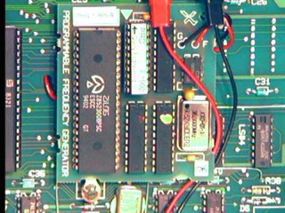 ( image courtesy of http://lisa2.com )
System 7 Notes
- Doing something useful with System 7 almost always requires more than 2 MB of RAM
- With a CPU board modification, you can use two 2MB memory boards to get 4MB
- Using an XLerator, up to 12.5 MB is possible, depending on the model and SIMMs used
- File Sharing
- Serving files requires an XLerator (the stock 5 MHz CPU is not fast enough to implement the protocols)
- The AppleShare client works with or without an XLerator
All versions of MacWorks Plus II work with or without the screen modification kit.
�(Comment on this answer)
4.7.1. What are the characteristics of Lisa Xenix?
Lisa Xenix is a Microsoft variant of SCO unix. The last version for the Lisa is 3.0.It supports multiple users via terminals connected to the built-in serial ports, as well as the Tecmar 4 port serial card.
Two add on packages require installation on a Widget hard drive, or a second ProFile (attached to dual a parallel port card). One is a development environment which includes a C compiler (K&R only, not ANSI) and a text based word processing suite called Lyrix.
Xenix does not support the Lisa's mouse, nor graphics; only text mode operations.
Hard Disk Size vs I/O board ROM version
Some portion of Xenix assumes that the size of the parallel port hard disk connected to the built-in port always corresponds to the type of Lisa. In particular:
- if the I/O board ROM is version A8, the hard disk connected to the built-in port must be 5 MB
- if the I/O board ROM is version 88, the hard disk connected to the built-in port must be 10 MB
Since 5 MB is too small to install everything in the Xenix distribution, on a Lisa 2 you may want to use an additional ProFile or use a modified I/O board ROM to make Xenix think it has a 10 MB drive. (You cannot just use the 88 EPROM instead, as the 6504 floppy disk controller code differs between them.)
Using an EPROM programmer, you can read the stock EPROM and burn a new one, changing the ID byte (at offset $1141) from A8 to, for example, $89 . This will make Xenix think the machine is a 2/10, and you can use a 10 MB drive on the built-in parallel port.
If you do this, make sure you label the EPROM carefully, as it won't work properly in a 2/10 I/O board. Hence the suggestion to use $89 in order to distinguish it from the real 2/10 ROM. The high 3 bits of the I/O ROM version are what Xenix uses to distinguish a 2/10 from a 2/5.
Note that other software (MacWorks, for instance), may look explicitly for I/O ROM version A8 or 88, and if the wrong ID is found, some parts of the software that depend on particular timing of the 6522 VIA chips may misbehave (eg. sound pitch may change, and AppleTalk may not work).
Thanks to Guido Deiana for assisting with this work-around.
�(Comment on this answer)