I was hoping to solve this on my own, but today I thought I needed to swallow my pride and ask for help.
The background: A Lisa 2/5 (with parallel card) plus two 5MB Profiles that I bought on eBay. The seller was in the LA area, and since my daughter lives there, she picked it up and brought it over to me in Palo Alto. This saved a few $100s in S/H. This 2/5 looks like it's actually a converted Lisa 1, as evidenced by the Twiggy power cable and the two floppy ribbon cables (see pic)
I was able to successfully reformat the two Profiles using the parallel card on one of my two 2/10. The CPU and both memory cards also tested OK. PS is good, after the two RIFA caps blew up and were replaced. The batteries of the 2/5 had never been removed, and the corrosion on the IO board and MB was extensive. I have not given up on the MB as yet, but decided to build a new one, using AlexTheCat123 github PCB info (Thanks !). I bought most of the components on AliExpress, and saved a ton of money (sorry Digikey...).This allowed me to do some good work on the IO board, and after replacing the 10uF Nichicon caps on the video board, taking the 400k FDD apart for de-seizing/lubing, removing corrosion on all sheet metal parts, retrobriting the case, and changing the light bulb in the on/off switch, I'm almost there.
I have a few remaining issues
1) The system boots only with one memory board in position Mem1. If I put the second board in Mem2, I have garbage on the screen
2) I still have the dreaded Error 57, stemming from the Disk Diag ROM test (documented in a previous post here). I did check that the Dskdiag signal (pin 11 on LS259 in U3E) was low, when it's high on my working 2/10
3) The keyboard is also not seen, nor do I have the "keyboard missing" error upon boot. The speaker also does not work
4) Past error 57, I can start booting from the Profile (with either MB or extension parallel ports), but get stuck after a while
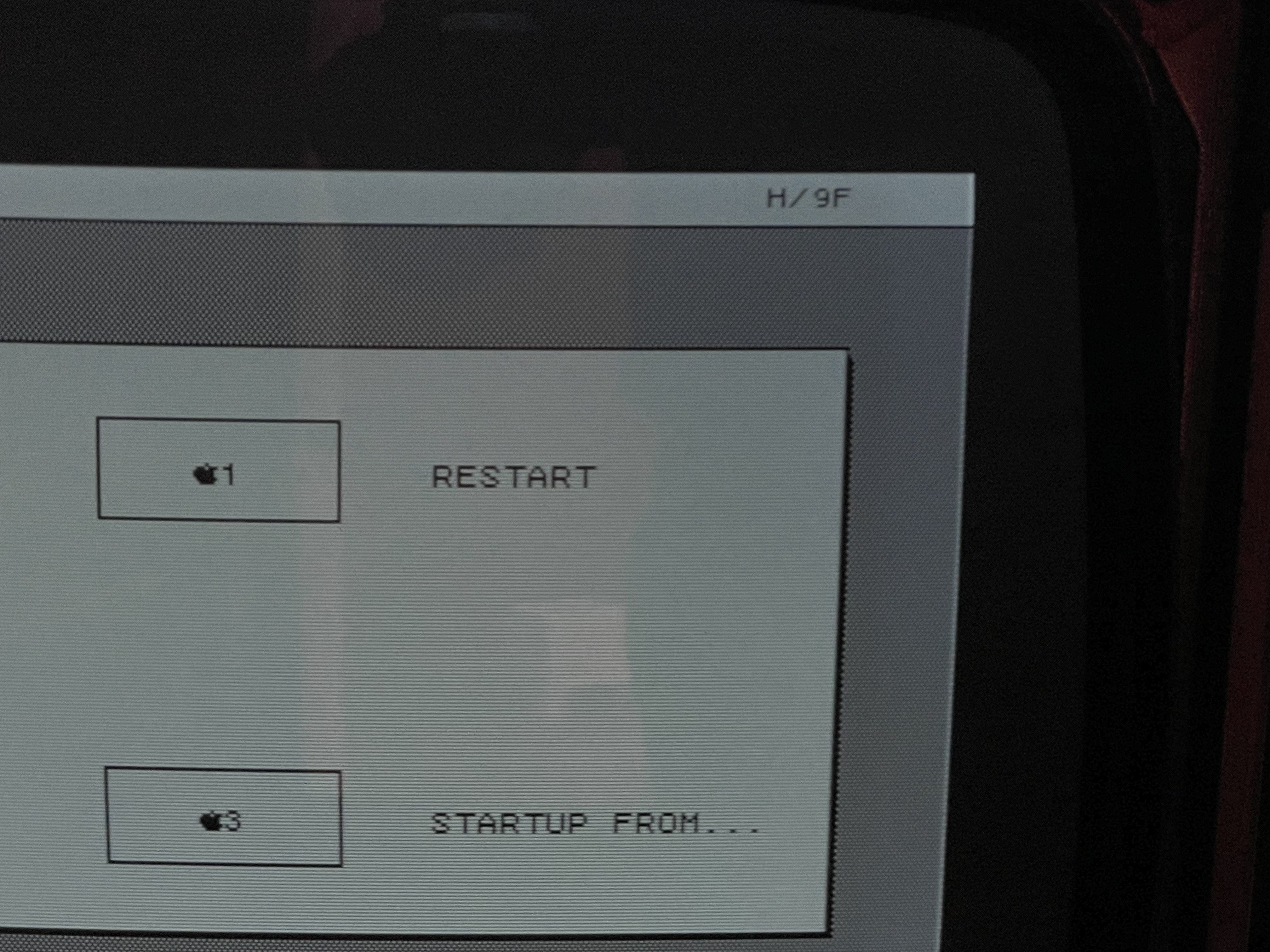
5) The IO ROM version which should be H/A8 shows H/9F or sometimes H/91 or H/9D (see pics)
6) My good 2/10 IO board also throws error 57 when placed on the 2/5, but displays the correct H/88 ROM versions. It also boots from the Profile, using my parallel card. After booting, it gives me a diskette error ("not a proper Lisa diskette" etc..)
7) I swapped all common socketed chips with my 2/10 IO board, including the VIA2 chips, with no progress
8 ) I tested the 400k FDD on my 2/10 and it works
Thanks for reading this. Any help would be much appreciated, especially from AlexTheCat123 if he has time. Some of the questions I have
1) There are two floppy cables (see pic). Does it matter which one we plug in (I tried both with no luck)
2) How is the dskdiag signal generated ? How can I test upstream of that, perhaps on the LisaLite adapter ?
3) Could the floppy/speaker/keyboard problem be related ?
3) The next obvious test would be to swap the IO ROM with a known good one. Would one of you be coming to VCF-West this weekend, and be kind enough to give me a loan of one for a day ?
Thanks in advance