- Welcome to LisaList2.
News:
I've successfully built LOS from source!: https://lisalist2.com/index.php/topic,644.0.html
Recent posts
#31
LisaList2 / Re: Minix on the Lisa
Last post by TorZidan - September 21, 2026, 09:42:28 PMHave not tried it, but this picked my interest:
"The make lisaem-* targets boot the images in LisaEm without anyone at the emulator, type commands and check the output."
I could not figure out how this works. Are you sending these commands over a serial port or somehow "typing them in LisaEm" (similar to the "paste host clipboard" menu item)?
Why is this important: if you are developing something for the Lisa using AI, it would be extremely useful to "tell" the AI how to launch LisaEm and how to compile and run and test your new app by moving the mouse, clicking, typing text, inspecting the Lisa screen, etc. This way the AI can run in a close loop, without your intervention, until it completes the task.
"The make lisaem-* targets boot the images in LisaEm without anyone at the emulator, type commands and check the output."
I could not figure out how this works. Are you sending these commands over a serial port or somehow "typing them in LisaEm" (similar to the "paste host clipboard" menu item)?
Why is this important: if you are developing something for the Lisa using AI, it would be extremely useful to "tell" the AI how to launch LisaEm and how to compile and run and test your new app by moving the mouse, clicking, typing text, inspecting the Lisa screen, etc. This way the AI can run in a close loop, without your intervention, until it completes the task.
#32
LisaList2 / Re: Minix on the Lisa
Last post by jamesdenton - September 21, 2026, 09:19:45 PM"You're absolutely right."
@AlexTheCat123 Agreed 100%, that is/was a bad assumption and I'll get that fixed.
@AlexTheCat123 Agreed 100%, that is/was a bad assumption and I'll get that fixed.
#33
LisaList2 / Re: Minix on the Lisa
Last post by AlexTheCat123 - September 21, 2026, 09:11:10 PMImpressive; so many things are being ported to the Lisa that it's almost overwhelming!
One quick note: The docs mention that the size of the hard disk image must be "exactly 5,175,296 bytes (9728 blocks) or 10,350,592 bytes (19456 blocks): ESProFile sets its spare table from the file size and only knows those two." This isn't true; ESProFile will happily accept an image of any size you want, and will make a custom spare table to match. That's how the 50MB LOS compilation image works. So you can have an utterly massive Minix disk if you want!
One quick note: The docs mention that the size of the hard disk image must be "exactly 5,175,296 bytes (9728 blocks) or 10,350,592 bytes (19456 blocks): ESProFile sets its spare table from the file size and only knows those two." This isn't true; ESProFile will happily accept an image of any size you want, and will make a custom spare table to match. That's how the 50MB LOS compilation image works. So you can have an utterly massive Minix disk if you want!
#34
LisaList2 / Re: Minix on the Lisa
Last post by bmwcyclist - September 21, 2026, 08:30:29 PMWow!!!!
#35
LisaList2 / Minix on the Lisa
Last post by jamesdenton - September 21, 2026, 08:10:03 PMIn the spirit of "all things on Lisa", I introduce to you a "port" of the Minix operating system for the Apple Lisa.
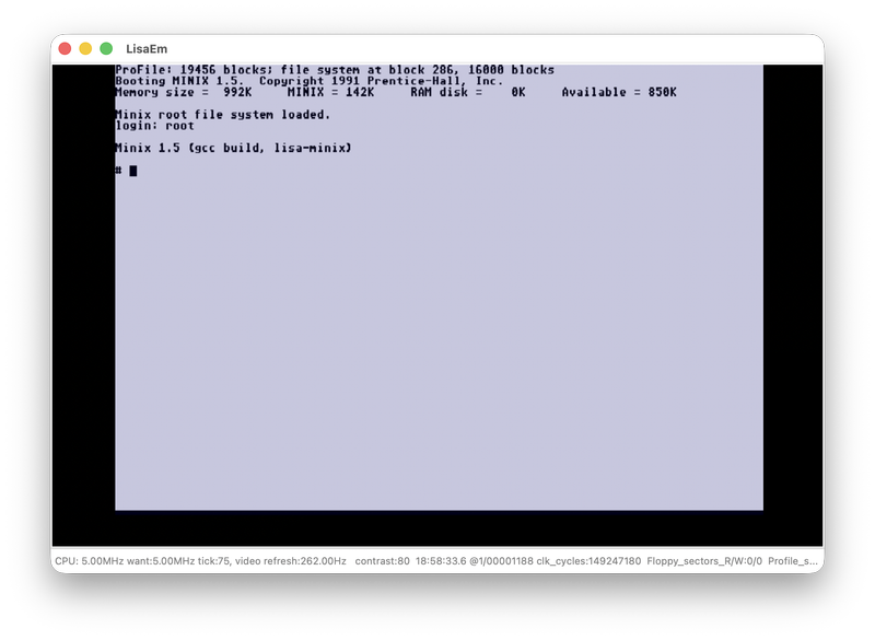
The repo https://github.com/arcanebyte/lisa-minix includes instructions for cross-compiling from macOS using gcc and also includes tooling to build out a ProFile image that's ready to go. Enjoy!
The repo https://github.com/arcanebyte/lisa-minix includes instructions for cross-compiling from macOS using gcc and also includes tooling to build out a ProFile image that's ready to go. Enjoy!
#36
LisaList2 / Re: I won a local auction for ...
Last post by TorZidan - September 21, 2026, 07:31:39 PMsigma7, are you a human?
I am growing more-and-more suspicious that you may be not:
You've been guiding berskyboy relentlessly to fix his power supply.
You've been posting voltage measurements of a working power supply, photos and custom-made schematics. I have't seen such level of dedication in humans...
Kudos if you are!
I am growing more-and-more suspicious that you may be not:
You've been guiding berskyboy relentlessly to fix his power supply.
You've been posting voltage measurements of a working power supply, photos and custom-made schematics. I have't seen such level of dedication in humans...
Kudos if you are!
#37
LisaList2 / Re: I won a local auction for ...
Last post by berskyboy - September 21, 2026, 07:12:54 PMQuote from: sigma7 on September 21, 2026, 06:48:52 PMWith the black lead on pin 5 of the daughterboard's connector, put the red lead on each of the other connector pins and measure with diode test mode, and again with resistance mode.
Black to Pin 5, Red to Pin x
Pin x DiodeTest Resistance Signal. Measurements
1 inf 6k +12 sense. 1.628
2 inf 10k line sense. 1.842
3 1.1 >5k +18V 0.949
4 inf 50k on/off. OL
- - - ground
6 inf 2.6k +5 sense. 1.196
7 inf 2.5k current sense. 1.163
8 inf >100k /shutdown. OL
9 inf inf /power fail. OL
10 inf inf pull. OL
11 inf inf push. OL
12 1.1 >1k logic +5. 0.871
13 inf inf /delay reset. OL
#38
LisaList2 / Re: I won a local auction for ...
Last post by sigma7 - September 21, 2026, 06:57:15 PMQuote from: berskyboy on September 21, 2026, 06:41:13 PMHere's a photo of the board and maybe some solder bridges? I thought the dot close together would be the same join?
The red arrows don't point to solder bridges as far as I can tell.
Referring to the black and white diagram, there should not be any solder that bridges across a white gap from one black section to a different black section. It can be very difficult to see a bridge in a photo, so you should look at the narrow white sections and carefully compare to your board.
#39
LisaList2 / Re: I won a local auction for ...
Last post by sigma7 - September 21, 2026, 06:48:52 PMRemove the daughterboard and check it while disconnected from the main board:
With the black lead on pin 5 of the daughterboard's connector, put the red lead on each of the other connector pins and measure with diode test mode, and again with resistance mode.
Black to Pin 5, Red to Pin x
With the black lead on pin 5 of the daughterboard's connector, put the red lead on each of the other connector pins and measure with diode test mode, and again with resistance mode.
Black to Pin 5, Red to Pin x
| Pin x | DiodeTest | Resistance | Signal |
| 1 | inf | 6k | +12 sense |
| 2 | inf | 10k | line sense |
| 3 | 1.1 | >5k | +18V |
| 4 | inf | 50k | on/off |
| - | - | - | ground |
| 6 | inf | 2.6k | +5 sense |
| 7 | inf | 2.5k | current sense |
| 8 | inf | >100k | /shutdown |
| 9 | inf | inf | /power fail |
| 10 | inf | inf | pull |
| 11 | inf | inf | push |
| 12 | 1.1 | >1k | logic +5 |
| 13 | inf | inf | /delay reset |
#40
LisaList2 / Re: I won a local auction for ...
Last post by berskyboy - September 21, 2026, 06:41:13 PMQuote from: sigma7 on September 21, 2026, 04:49:48 PMI'll work on some measurement instructions to look for further failures on the daughterboard. In the meantime:
Use the image below to diligently check for any remaining solder bridges. If any remain, then Q1 and Q2 may be destroyed again after replacement, and further parts may be damaged too. Shiny solder joints hide subtle details, so after fully checking it once, it can be helpful to rotate the board and check again from a different angle.
If you find any bridges, take a picture/make a note of where they are as that information can help locate and/or eliminate additional components to suspect.
Here's a photo of the board and maybe some solder bridges? I thought the dot close together would be the same join?
https://www.dropbox.com/scl/fi/hw98nypaj0xsqwhhfgoer/Soldure.Bridges.heic?rlkey=sa3nlcvognw0gys8tra246itb&st=dzc64371&dl=0